
An underlay places an existing plan behind the model in 2D → Top. Import it onto a saved Level, establish its real dimensions, then draw your elements over it. The project owner needs Pro or Team. Project members can view references; only people with model-editing permission can import or change them.
Import onto the working Level
- Select the working Level and switch to 2D → Top. Save a newly created Level before importing.
- Open File → Level underlays… and choose a file in DXF, PDF or image.
- Set the format-specific options below, then choose Import underlay. Wait for processing to finish. Only one import can run in a project at a time.
- Close the panel and use Fit if the reference is outside the current view.
On a Level without loaded references, the import dialog stays centered with the editor blurred behind it. Selecting a file or starting an import keeps it there. Once the first reference has loaded, the panel slides to the upper-left corner below the command toolbar and the blur clears, so you can check its position against the plan.
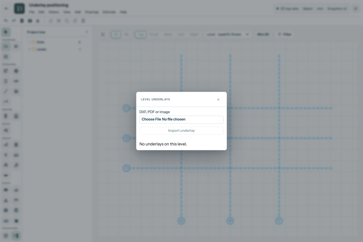
View the full-size import screenshot.
If processing cannot reconnect after a queue error, choose Retry import. It resumes the stored operation without selecting or uploading the file again, including after reopening the project.
| File | Before importing |
|---|---|
| DXF | Leave DXF units at Auto when the file declares its units. If they are missing or unsupported, choose the correct mm, cm, m, in or ft value and retry. Do not guess from how large the drawing looks. |
| Select PDF page and inspect its preview. If you know the printed drawing scale, enter its denominator in Drawing scale 1:N: for 1:50, enter 50. Otherwise leave it blank and calibrate after import. Only the selected page is imported, as an image. | |
| PNG, JPEG or WebP | Import the image, then calibrate a known distance. Its initial displayed size is provisional. |
DXF files can be up to 20 MiB, PDFs 50 MiB, and images 25 MiB. A Level can hold 10 references and a project 50. Very large or complex files may exceed processing limits; simplify the source drawing or use a smaller image. Convert DWG to DXF and SVG or TIFF to a supported image format before importing.
DXF imports model-space lines, curves and supported outlines. Text, dimensions, external references and unsupported content may be skipped; read any notices beside the imported reference. A PDF or image preserves visible annotations as pixels, but does not provide individual drawing points for snapping.
Set the real scale
For a scan or a PDF without a reliable printed scale:
- Reopen Level underlays… and find the imported reference. Clear Locked if necessary.
- Enter the real distance between two identifiable points in Measured length mm. For example, a known 4 m span is 4000 mm; use the distance from your own plan.
- Choose Calibrate two points. The panel closes. Click those two points on the reference in order. You can pan and zoom while locating them.
- After the second point, the reference changes size and the panel returns. Check a second known dimension before tracing.
Calibration applies one uniform scale. It cannot correct a skewed photograph or a distorted scan. Use a straight, undistorted source image when distances need to agree across the plan.
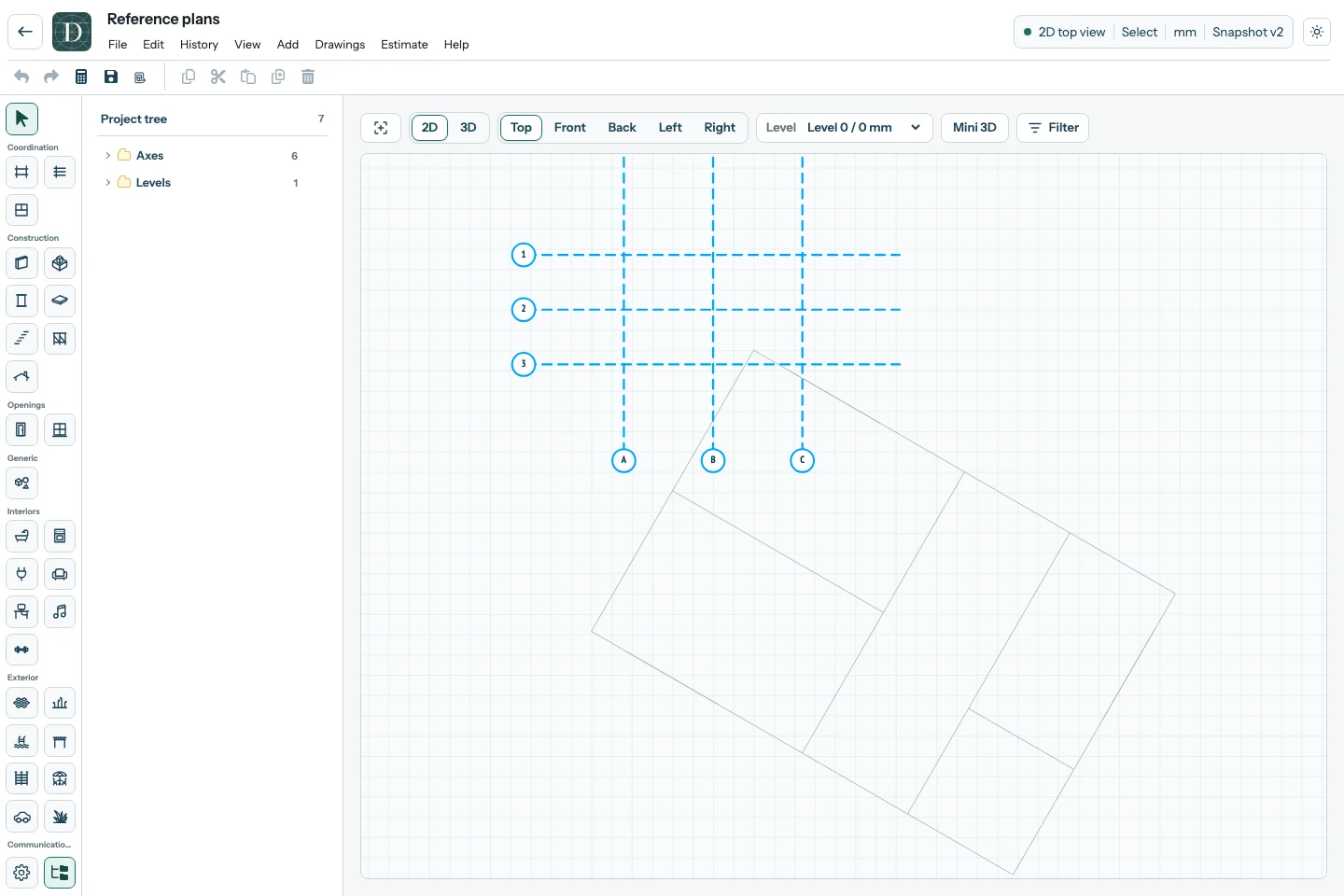
View the full-size underlay screenshot.
Position and align the reference
Opening Level underlays… returns to Select, clears the object selection and closes the right-hand tool panel. If references are already loaded, the panel opens directly at the upper left. It keeps that corner fixed as its contents change, and the plan stays clear while you adjust the reference.
Use X mm, Y mm and Angle ° to translate or rotate the reference. mm / source unit controls its scale: a source unit is a drawing unit for DXF and a pixel for an image. Prefer two-point calibration when you know a measured distance rather than this ratio.
To match two reference points to two project positions, choose Align two pairs. Click the first and second source points on the underlay, then their corresponding first and second destination points. The reference moves, rotates and scales to match that pair. Choose Cancel to leave the placement unchanged.
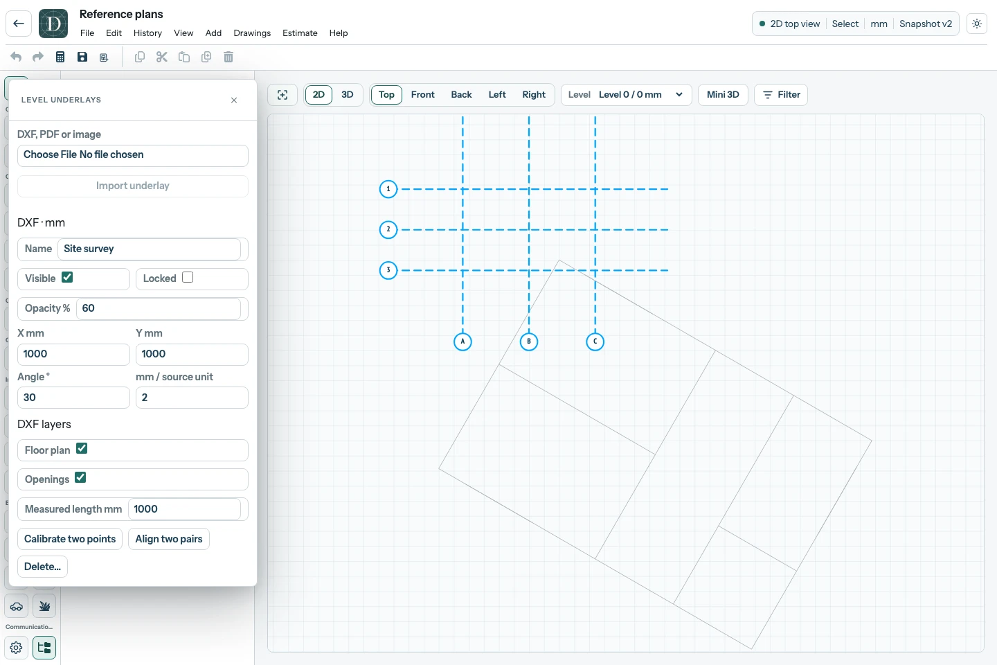
View the full-size settings screenshot.
Set Locked when the placement is correct. Locking prevents transforms and calibration; it still allows changes to the name, visibility and opacity. Visible, Opacity % and the DXF layers checkboxes help keep the model readable. New references start at 50% opacity.
Trace and check the result
Draw a Wall, Floor, Terrain, Pavement or Pool over the reference. On a calibrated DXF, supported original endpoints and vertices can produce a snap marker. Hidden references, hidden DXF layers and references at zero opacity do not provide snap points. PDF pages and images require visual tracing, even after calibration.
Snapping places a model point; it does not bind the new element to the underlay. Later changes to the reference do not move traced elements. See snaps and guides for the other placement controls.
Saving, removal and sharing
Underlay changes save immediately, independently of model Save and Undo/Redo. Reopening the project retains them. They appear only on their own Level in Top 2D, and are excluded from side views, 3D, drawing sheets, PDF/DXF exports, estimates and the public viewer.
Saved versions keep the model, not copies of underlays. Restoring a model retains references on Levels that still exist and removes references whose Levels disappear. Deleting a Level or the whole project also removes its references. To remove one yourself, choose Delete…, then confirm Delete underlay; this cannot be undone.
If the owner's subscription becomes Free, references remain stored but cannot be viewed or changed until the project has access again.