
Communications → Pipes → Water supply draws a connected spatial route with straight pipes and catalog fittings. The current tool starts a Cold water network from a compatible Water heater connection. It does not start from an arbitrary point in empty space.
Prepare the connection
- Place or select a Water heater.
- In its right panel, open Connection profile and choose G½ flat-seal. Not specified provides no usable connection for this tool.
- Set the heater's Level, dimensions, Floor offset and Rotation before connecting it. Those choices locate the connection in space.
- Choose Pipes → Water supply. Wait for the catalog to load. The current selection is Cold water, section d20 × 2.25, with fixed 90° turns.
The eligible cold_in port must be unbound and compatible with the chosen pipe. The port marker is the starting target; the heater body or another decorative appliance part is not a connector.
Draw the route
- Use 2D → Top, 2D → Front or 3D → Isometry. To set a 3D view before starting the route, switch to Select, choose Iso or Perspective and orbit until the connection is clear. Then choose Pipes → Water supply again. See 3D navigation.
- Hover over the eligible cold_in port and click the snap marker. The tool derives the terminal elbow and the first outgoing work plane from that connection.
- Move the pointer until the valid horizontal preview reaches the next turn, then click.
- Press Z to lock the next run to the vertical axis through the last point. Click a valid vertical preview to set the next elevation. Press Z again to return to horizontal authoring.
- Continue with valid points, then press Enter to commit the route. Backspace removes the latest draft point; Escape discards the active draft.
The right panel shows Work plane, Elevation, Z axis and each route point's X/Y/Z coordinates. Check those coordinates rather than judging height from the camera alone. You can switch Top, Front and 3D during the draft; other side views display the route but do not author it.
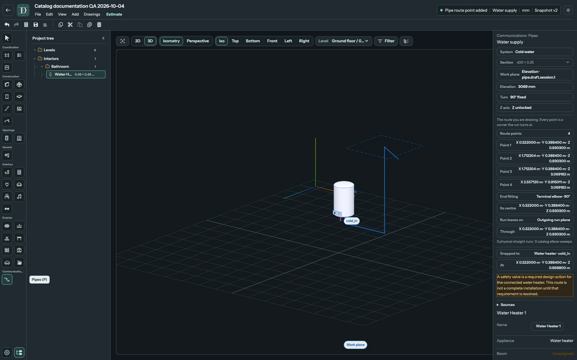
View the full-size screenshot. The shown dimensions and elevation are example choices.
Check what was created
The Project tree lists the Pipe network and its segments, nodes, fittings and ports under Pipes. The network belongs to the Building's plumbing system; its connected heater remains a separate interior object. Select a segment, fitting or node to inspect that part, then save and reopen.
The panel retains a required safety-valve design warning for the connected heater. The route is a coordination model and does not resolve that requirement. Current authoring does not add branches, merge networks, connect a second appliance, generate a complete installation or perform hydraulic sizing. Continue with Inspect and edit a Pipe Network.