
A Roof window lies in a roof surface and creates an opening in that surface. It stays attached to one supporting face. Use it on an inclined slope or as a horizontal rooflight on a Flat Roof. Use a dormer for a vertical projecting window on a pitched roof, or a glazed gable fill at the roof end.
Create a window in a roof surface
- Select a resolved Roof in Top, with a view Level that shows its surfaces.
- Open Slopes and select the supporting surface. The same slope highlights in the model and project tree.
- Select Add window inside that slope. Choose Roof window in Type, then select Add window. The complete window appears at a valid position near the slope's center. No drawing or placement clicks are required; Cancel closes the dialog without changing the model.
- With the new window selected, set Width along slope, Height along slope, Across slope and Up slope. Choose Frame width, Frame material and Glazing material, then use Apply changes after validation.
- Inspect Top, a side view and 3D; Save when the result is correct.
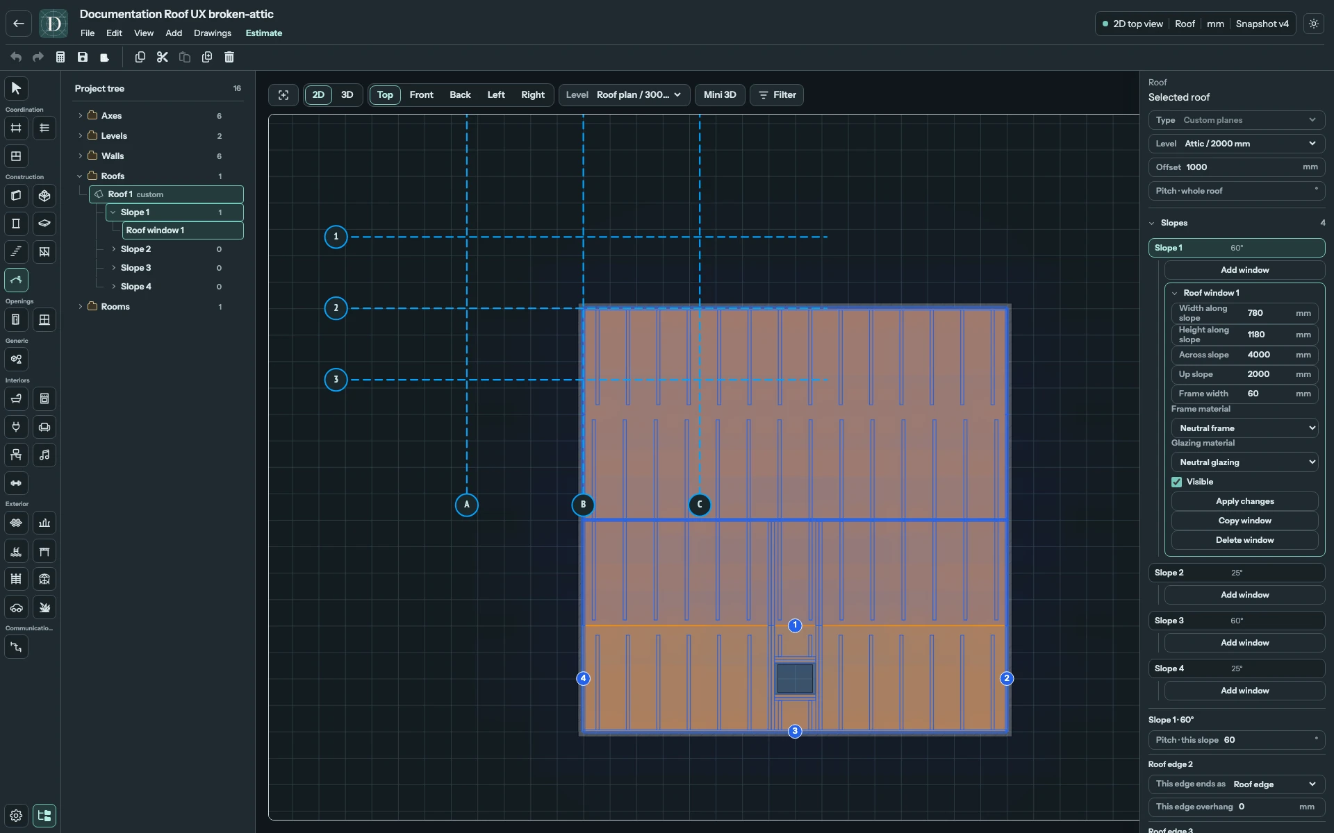
View the window settings at full size.
The position fields are surface coordinates, not global X/Y. Across slope measures the center along the face's reference boundary; Up slope measures it upward within that plane. Both dimensions also lie in the plane. For example, a 1,180 mm high window on a steep slope does not occupy 1,180 mm in horizontal Top projection. Use your own window dimensions rather than copying the example's values.
Place a rooflight on a Flat Roof
Select the Flat Roof's 0° surface under Slopes, then follow the same Add window steps with Roof window as the type. The field labels remain Width along slope, Height along slope, Across slope and Up slope. On this horizontal surface, both dimensions and both position coordinates lie in the horizontal roof plane; changing Up slope does not raise the window.
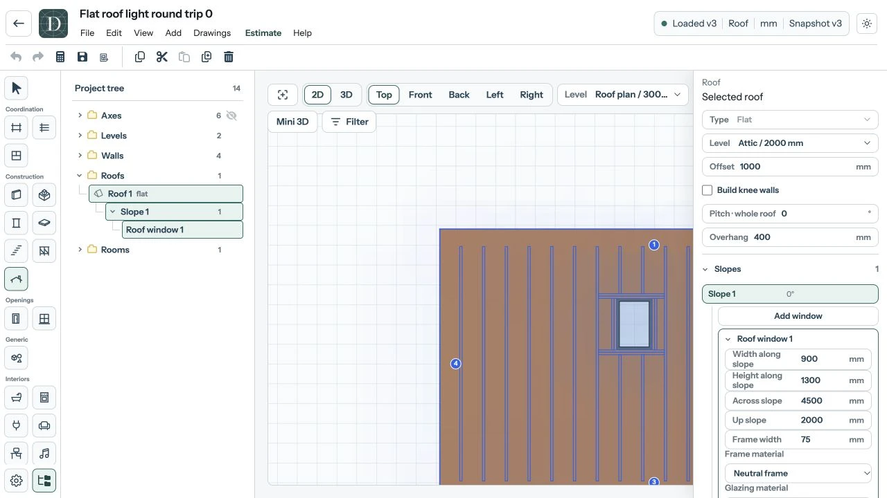
View the flat-rooflight example at full size.
Inspect the opening and framing in Top and 3D before saving. This is a neutral architectural rooflight model; choose the actual product and installation details for your project. The model does not verify waterproofing or drainage. A Dormer window requires a pitched host and cannot be placed on this horizontal surface.
Dimensions, materials and visibility
| Field | How to choose it |
|---|---|
| Width along slope, Height along slope | Positive dimensions measured in the roof plane. The full frame and opening must fit the selected patch. |
| Across slope, Up slope | Coordinates of the window center in that plane; their allowable range depends on its boundaries and other openings. |
| Frame width | Positive frame border. Twice this value must be smaller than both window dimensions so glazing remains. |
| Frame material, Glazing material | Assign catalog materials independently. Neutral frame or Neutral glazing leaves that part without an explicit material assignment and uses its neutral appearance. |
| Visible | Changes the child's display after Apply changes. It does not close the opening. |
These fields prepare a draft. Use Apply changes to commit dimensions, materials or visibility together; the previous committed window remains intact until that command succeeds.
Keep the opening within a valid host
One opening must fit in one connected physical patch of its selected face. Keep it inside the legal host area, clear of boundaries, ridges, valleys and other openings, with room for the required framing. A visually overlapping outline is not sufficient to make the placement valid.
If Add cannot find space, read the placement message and choose another slope or adjust the Roof. When Apply changes, or a copy's Create window, is unavailable, change the proposed size or center. Try moving away from the boundary. A rejected proposal keeps the prior committed window and Roof intact.
Move a window on its slope
Choose Select, then drag the visible window in Top, a side view or 3D. Movement stays on its current supporting slope. The window stops at the first invalid position, such as a boundary or another opening; dragging cannot carry it through that obstacle or onto a different slope.
Top converts the mouse movement into across-slope and up-slope distances. A side view exposes only the directions visible in that projection; an end-on view may allow only movement up the slope. Use Top or the coordinate fields when the side view cannot show the direction you need. In the main 3D view, drag the window itself; its position follows the host plane rather than moving freely in space. The small 3D preview updates after edits but does not provide this direct editing gesture.
Release the mouse to finish. One accepted drag is one Undo operation. Press Esc during a drag to cancel it. To resize, use the dimension fields and Apply changes. See view navigation for moving the camera instead.
Work on a broken or mansard roof
Select the particular lower or upper face before adding the window. A window belongs to that plane; it cannot span the break where the pitch changes. The example below uses a previously defined broken roof with steep lower and shallower upper surfaces. Its window sits wholly within one lower surface.
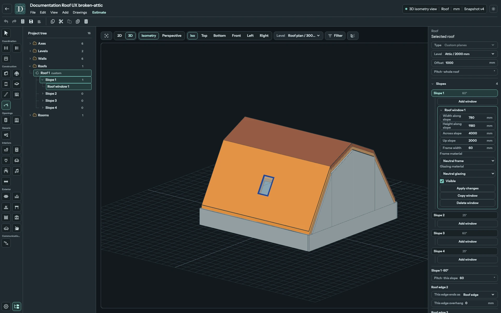
View the broken-roof example at full size.
Select the lower or upper surface under Slopes and use Pitch · this slope to change that plane's angle. Pitch · whole roof changes the Roof's applicable pitches together. Check the pitch break and the window's fit after either edit; see Custom planes and individual pitches.
Edit, copy, hide and delete
Open the window child beneath its slope in Slopes, or select it beneath that slope in the project tree. Change its dimensions, center or materials and use Apply changes after validation. Copy window prepares a draft at an offset position; adjust it to a clear area and select Create window. Unlike Add, Copy requires this confirmation. The resulting copy has its own identity and remains hosted by the Roof.
Visible controls the window's display after Apply changes. Hiding it does not fill its roof opening. Select the actual window row and use Delete window, or press Delete while that child is selected, to remove only the window and restore the surface and framing. The Roof stays in place. In main 3D, switching the Roof's Show shell off exposes its framing while a Roof window with Visible on remains displayed. Use the child's own visibility when you want to hide it. Removing the supporting Roof also removes its owned windows. Undo can reverse the completed change.
Inspect framing, drawings and estimates
Use Show shell to expose the framing. Compare the same Roof before and after adding the window: the rafter lines stay in place while affected members are interrupted locally.
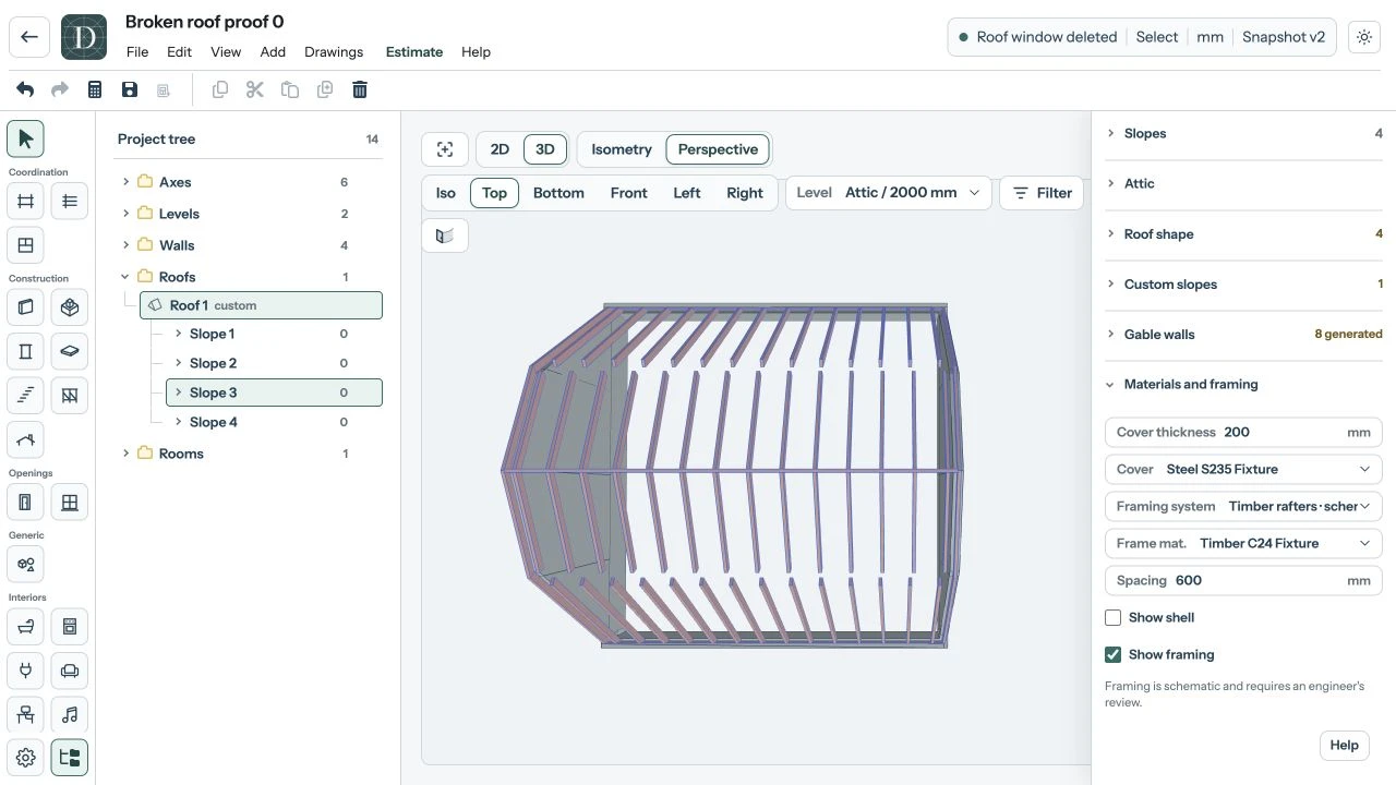
View the framing before the opening at full size.
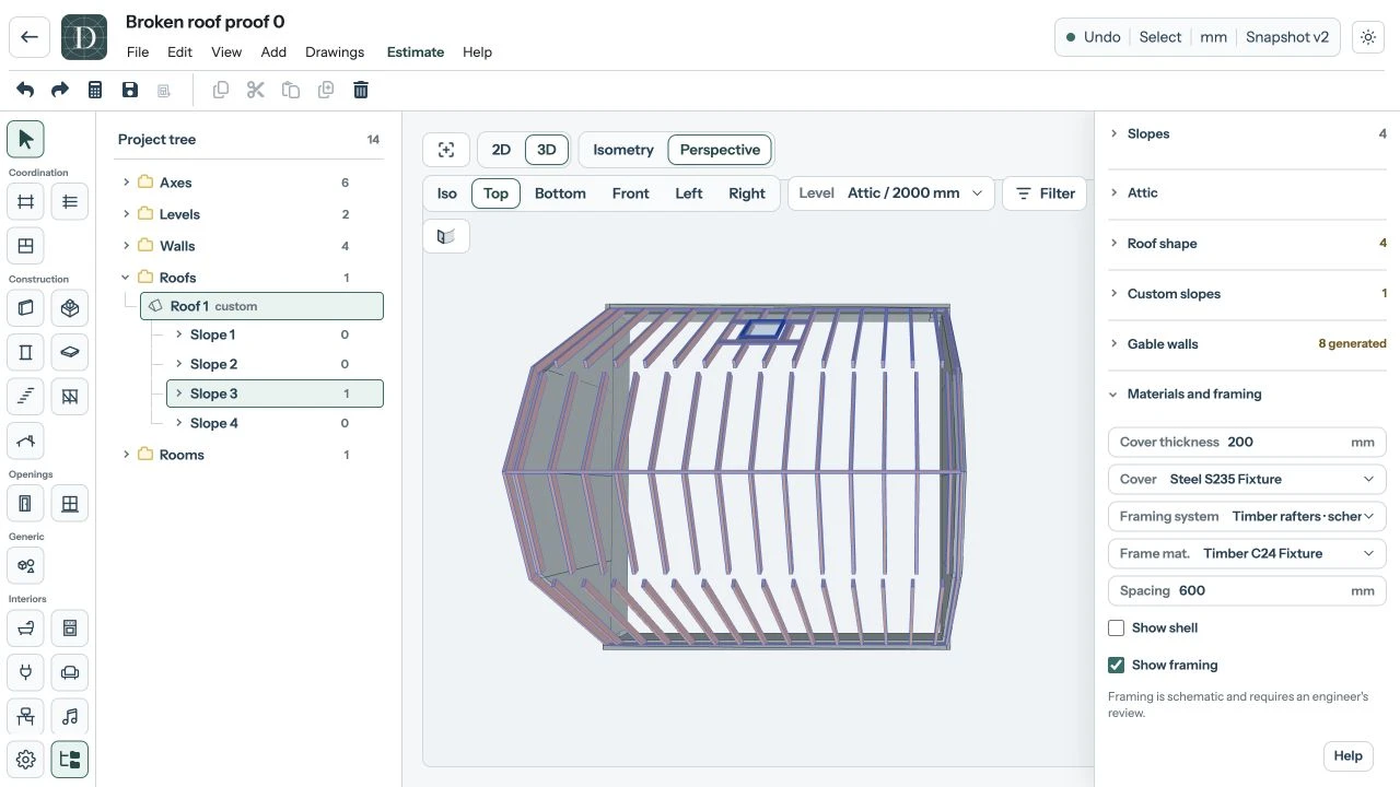
View the framing example at full size.
A supported timber-rafter roof keeps the original rafter lines and spacing. The opening interrupts the affected rafters at local headers; short doubled side members stay between those headers. Adding a window does not move the rafters or add full-length rafter lines beside it. Flat joists · schematic follows the same rule for joists. On a broken roof, the window's local frame stays within its host panel.
The local headers must reach retained rafters or joists on both sides without crossing another opening or the roof boundary. Local frames must not overlap or cut off another window's header supports. A placement that cannot fit this framing is blocked, as is an unsupported truss cut. The visible arrangement is a modeling result; it does not establish member sizes or structural capacity. See Roof materials and framing.
Drawings show the resulting geometry; the window's declared width and height remain its dimensions in the roof plane. In an estimate, the finished Roof window is a separate item, while roof covering and framing reflect the opening. Check missing-price messages rather than treating an unpriced window as zero cost.