
An elevation shows the model from one side. A section cuts through it to reveal the construction crossed by the plane. Choose the viewing side, then turn Show section cut on when you need a section.
Set an elevation
- Switch the editor to 2D → Top, open Drawings → New drawing sheet… and choose the relevant Level. The command is unavailable in 3D and in side views; the side is chosen in the next step.
- Choose View → Front, Back, Left or Right.
- Leave Show section cut off. Check the visible outline, openings and supported elevation marks.
- Enter Name and choose paper, scale and presentation. Fill the title block, then Save drawing.
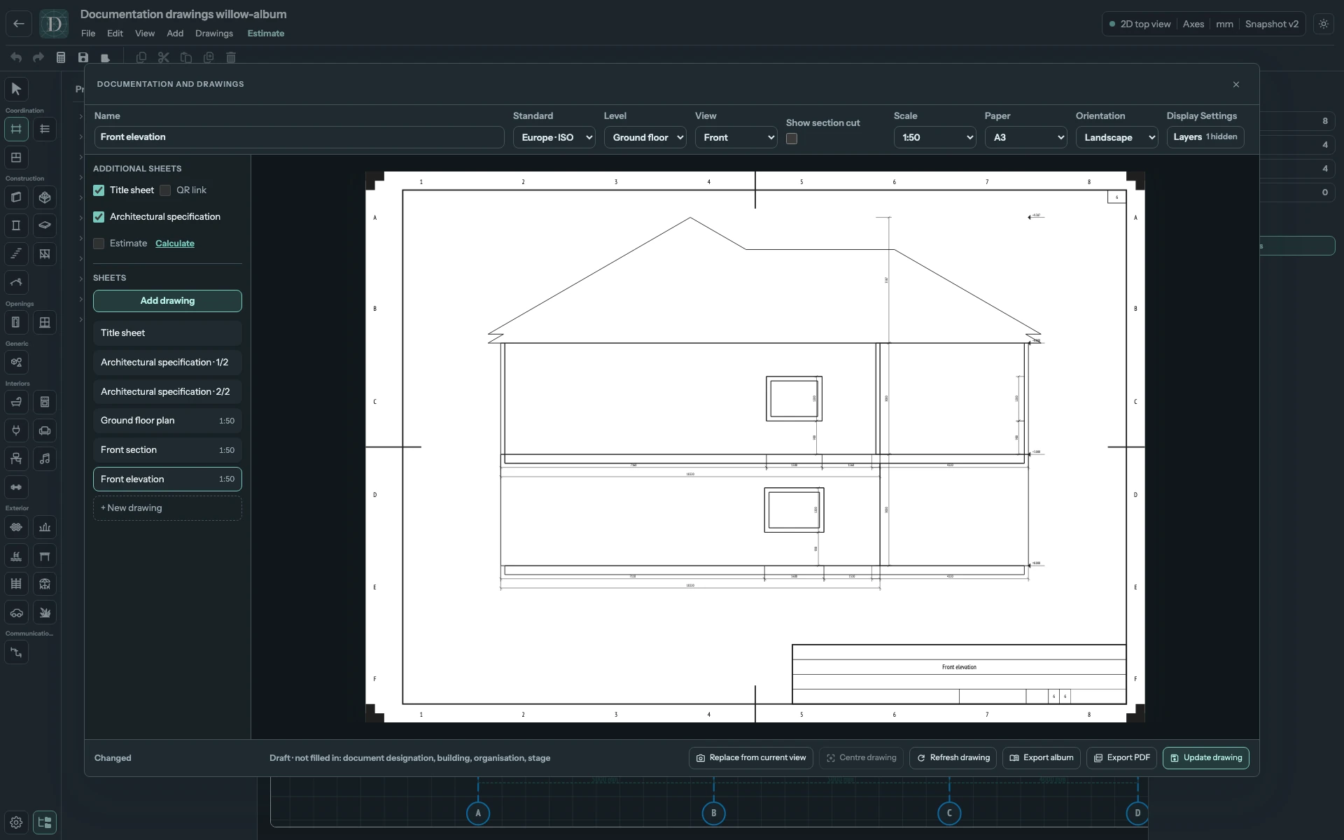
View the full-size screenshot.
Place a section through the building
Turn Show section cut on. Section cut location appears beside the preview. Drag its red line in the small Top key plan, or enter the depth beneath it. Wait for the refreshed drawing before judging the result.
| Control | Meaning |
|---|---|
| Front, Back, Left, Right | Direction from which the elevation or cut is viewed. |
| Show section cut | Available for these four side views. Off gives an elevation; on gives a section. |
| Section cut location | The Top key plan locates the cutting plane relative to the model. Drag its line to reposition it. |
| Depth field below the key plan | Model-coordinate depth in metres along the selected direction. Negative values can be valid. Choose the position from your model rather than copying the example. |
The two examples below use the same Front direction and scale. Moving the plane from depth 0 m to 3 m changes which construction it crosses. Recheck Walls, floors, Roof, openings and the small key plan printed on the sheet.
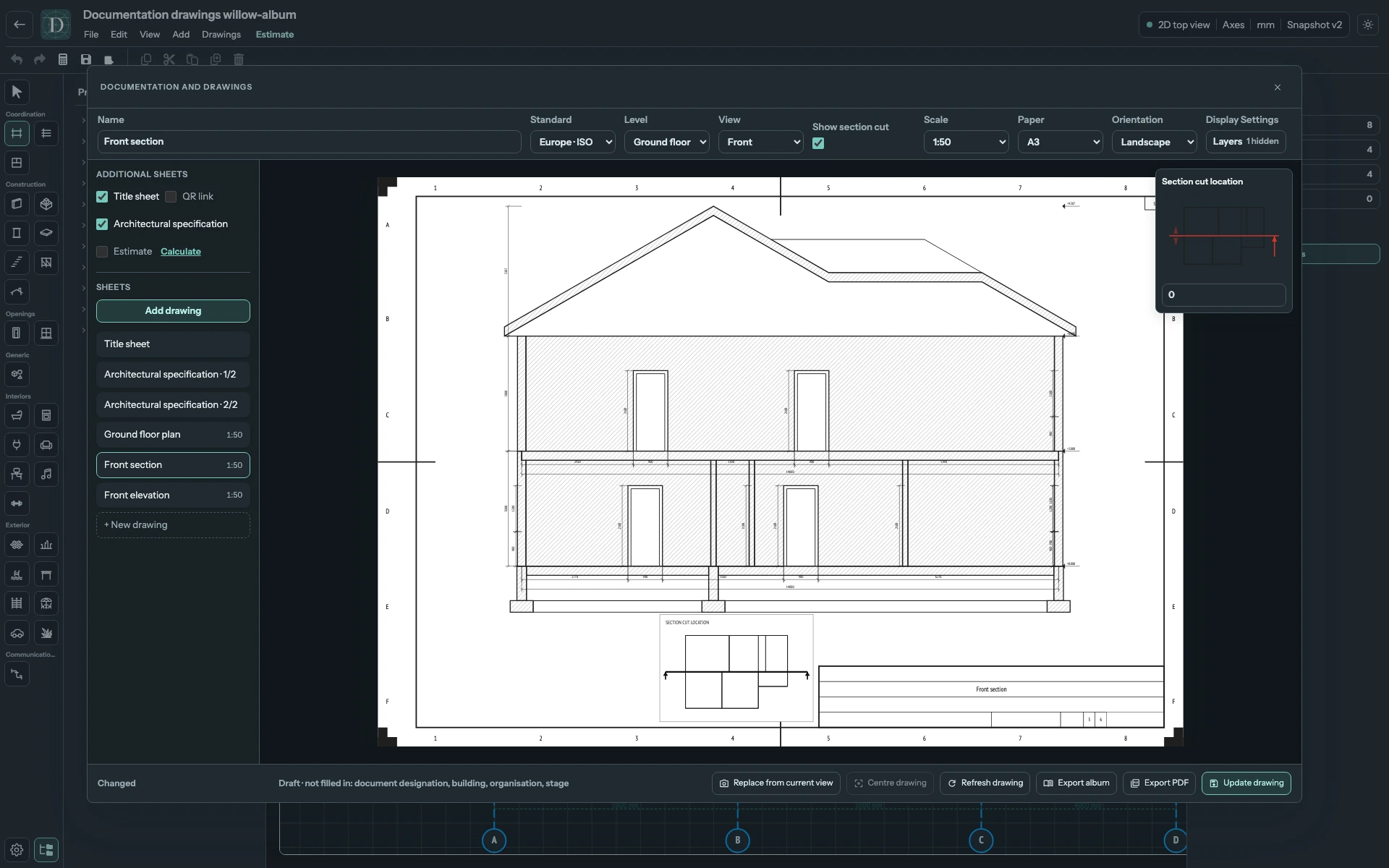
View the full-size screenshot.
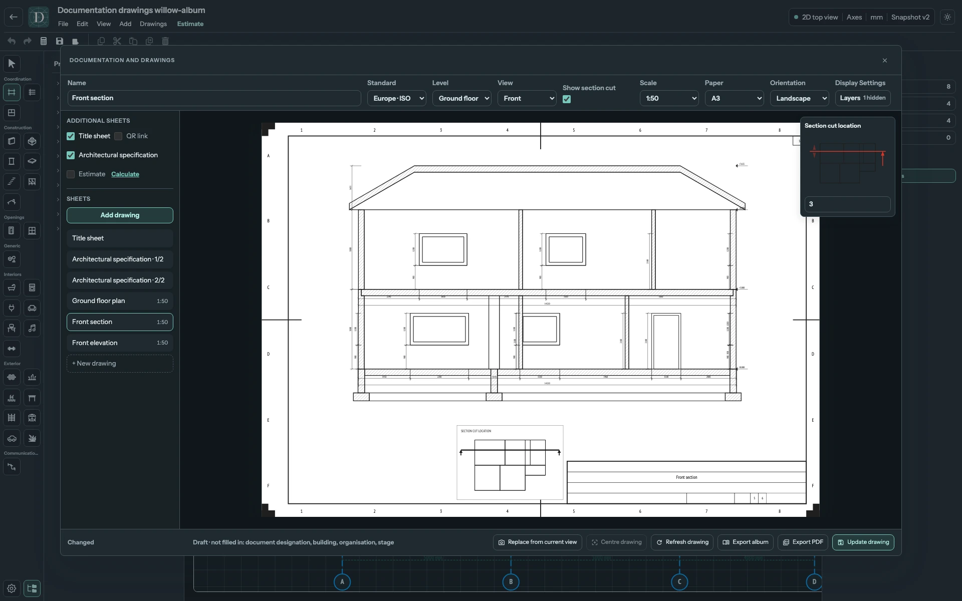
View the full-size screenshot.
Changing the viewing side changes how the depth is interpreted; inspect the key plan after every direction change. Top and 3D have different controls and do not offer this side-section toggle. Name, save and reopen the accepted section before adding it to the album. The cut is a model-derived drawing, not an engineering check.