
Floor creates a physical slab from a closed polygon. Use it for a horizontal floor envelope and for full-depth openings. It appears under Slabs in the Project tree. A Room is a separate named spatial boundary; drawing a Room does not create a Floor.
Draw the footprint
- Open 2D → Top, choose Floor under Construction, or press F.
- Choose Level, Binding, Offset, Thickness, Material and Assembly in the right panel.
- Click successive corners of the outside boundary. Follow the preview and snap marker for Axes, Wall corners or Wall sides.
- Click the first point again to close the polygon. A valid polygon creates one Floor. Esc cancels an unfinished sketch; Backspace removes its last point.
Use the visible drafting controls for Free/90° angles and free or stepped lengths when needed. A stepped length belongs to your drafting setup; choose a step suitable for your design. The polygon must have at least three points, positive area and no self-intersection.
Choose which face follows the Level
| Binding | Vertical result |
|---|---|
| Top | The top face is at Level elevation plus Offset. Thickness grows downward. |
| Bottom | The bottom face is at Level elevation plus Offset. Thickness grows upward. |
Offset is signed: positive raises the selected reference plane and negative lowers it. Thickness is the distance between the two faces, with a minimum of 40 mm. For example, Top binding at Level 0, zero offset and 240 mm thickness places the bottom at -240 mm. The value is an example, not a required slab thickness.
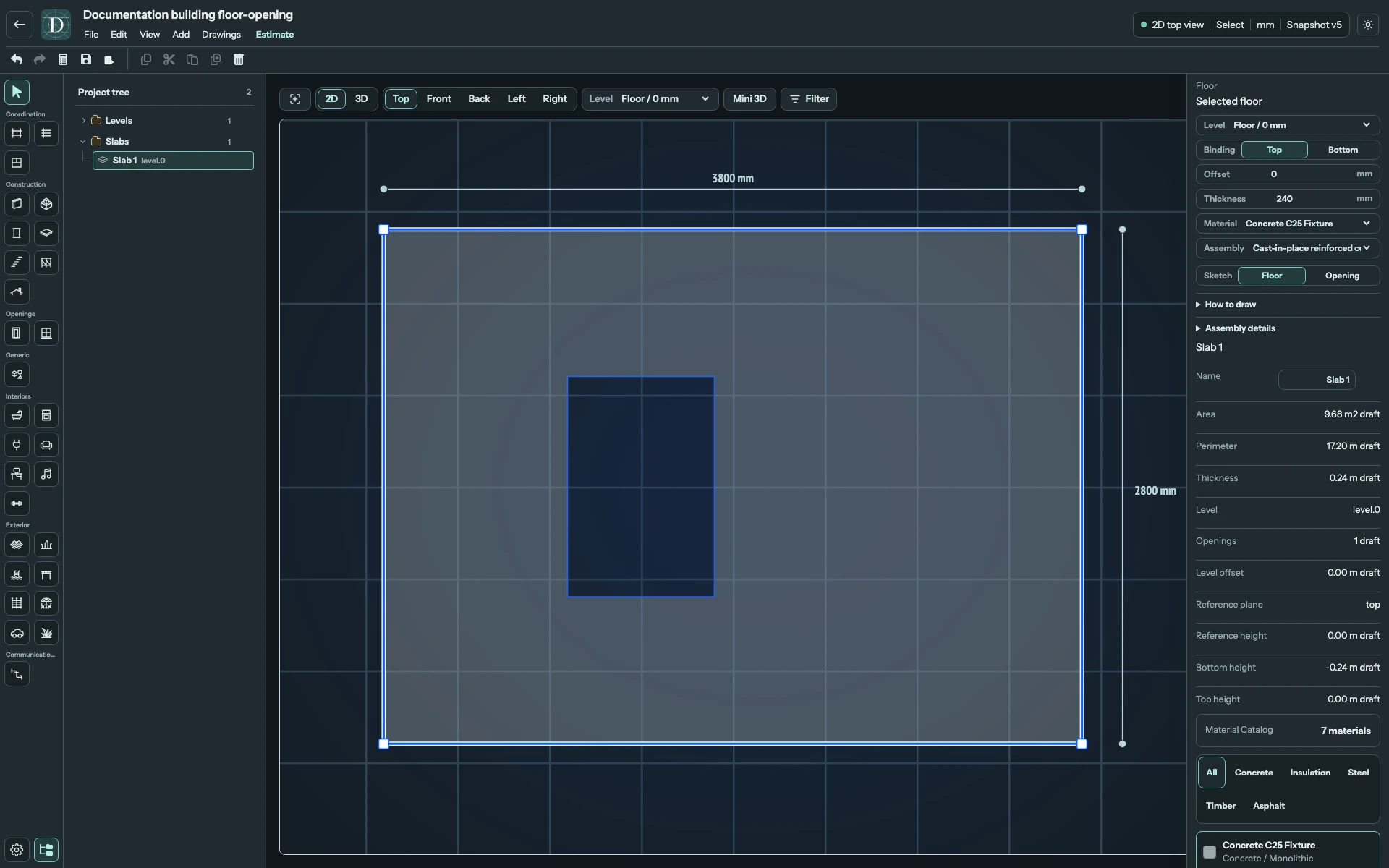
View the full-size screenshot.
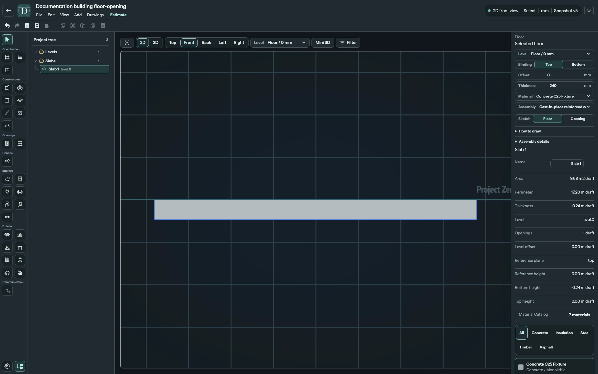
View the full-size screenshot.
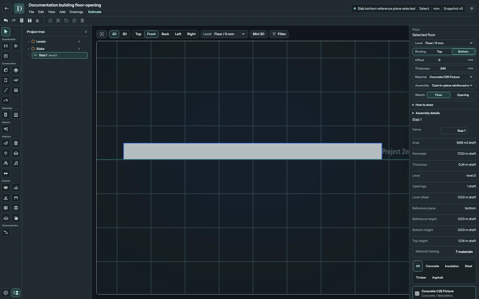
View the full-size screenshot.
Floor settings
| Field | What it changes |
|---|---|
| Level | Datum for the selected reference face. |
| Binding | Top extends thickness downward; Bottom extends upward. |
| Offset | Signed distance from the Level to that face. |
| Thickness | Slab envelope depth, at least 40 mm. |
| Material | Primary material assignment; the selector excludes insulation materials. |
| Assembly | Floor system preset; selecting one also applies its primary material and default thickness. |
| Sketch → Floor / Opening | Chooses an outside footprint or an inner full-depth cut. Opening requires a selected Floor. |
| How to draw | Expandable instructions for the current sketch. |
| Assembly details | Summary, modeling note and source label for the selected system. |
| Name | Instance label in the selected object's inspection fields, up to 120 characters. |
The read-only inspection values report Area, Perimeter, Thickness, Level, Openings, Level offset, Reference plane, Reference height, Bottom height and Top height. In the study, outside area is 10.64 m² and the opening is 0.96 m², leaving Area 9.68 m². Perimeter includes the opening boundary: 13.20 m outside plus 4.00 m inside gives 17.20 m.
Choose the assembly
| Assembly family | Default modeling envelope |
|---|---|
| Cast-in-place reinforced concrete | 200 mm concrete slab. |
| Precast prestressed hollow-core | 200 mm precast unit envelope. |
| Composite steel deck and concrete | 150 mm combined envelope. |
| CLT | 160 mm timber panel envelope. |
| Engineered timber I-joist | 300 mm floor zone envelope. |
Preset thicknesses are initial modeling values, not span or load approval. You can change Thickness after choosing the assembly. Choosing another assembly reapplies its default thickness and primary material; review those fields after the switch.
Material identifies the primary material. Assembly identifies the floor system. The catalog includes cast-in-place concrete, precast hollow-core, composite steel deck with concrete, CLT and timber I-joist families. Expand Assembly details to read its summary and modeling note.
These systems currently use a modeling envelope. Selecting hollow-core or I-joist does not create all internal voids or repeated members, and the displayed thickness is a preliminary modeling choice. Do not read an envelope as a complete layer or reinforcement design.
Reshape and make an opening
Select the Floor in Top. Hover a boundary vertex to reveal its grip and delete control; drag the grip to reshape it. Hover an edge to reveal + and add a vertex. With only three vertices left, the vertex delete control deletes the Slab. Floors have boundary controls rather than a whole-object move grip. Move and reshape compares the available controls.
For a full-depth cut, select one Floor and choose Sketch → Opening. Draw a closed inner polygon, then click its first point. The contour must lie within the slab, avoid the outside edge and avoid existing openings. A valid contour subtracts an opening through the complete thickness. Esc cancels the unfinished opening.
The current sketch does not provide individual opening-boundary editing, nested islands, sloped slabs or curved edges. Plan the opening before committing it; Undo reverses the last addition. A Stair can use its own slab-opening relationship, so inspect both objects when the stair route changes.
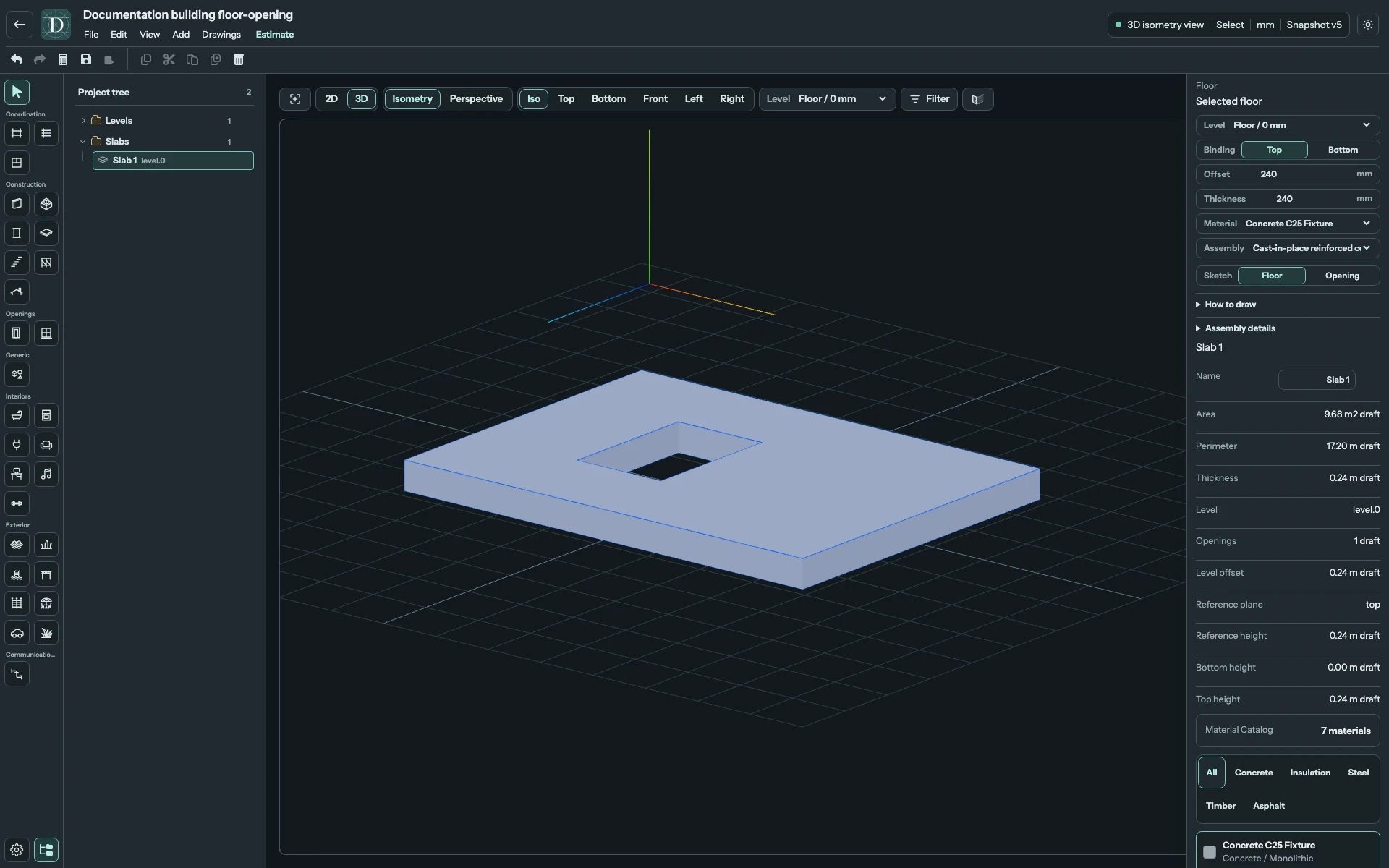
View the full-size screenshot.
Use Delete on the selected Floor to remove the slab and its openings; Undo restores an accidental deletion.
Check the footprint in Top, the reference plane in a side view, and the slab and cut in 3D. Save and reopen to verify the geometry and assembly.