
A Stair connects two elevations with equal-height steps. Flight creates straight runs joined by landings; Spiral creates radial steps around a center. The tool calculates the whole step count and rebuilds the route, railings and linked floor opening when its settings change.
This page covers both types and every setting in Selected stair. The examples connect Ground floor at 0 mm to Upper floor at 3000 mm. Their dimensions illustrate the controls; choose values appropriate to your own project.
Create and select a Stair
- Create the required Levels, switch to 2D → Top, then choose Stair under Construction.
- Choose Type: Flight or Spiral. Set Base level, Goes up to and the offsets.
- Choose Step rule, then set the step dimensions. Check the calculated rise, count and actual step height.
- For Flight, click the starting point, then click to set the upward direction. The second click sets direction; the calculated run determines the endpoint.
- For Spiral, click its center, then click to set the first radial edge. Steps ascend in the selected Rotation direction.
- Select the result in the working view or under Stairs in the project tree. The right panel becomes Selected stair and edits this Stair.
Esc cancels unfinished placement. With no Stair selected, the panel sets defaults for the next placement. A Stair belongs to its Base level; its top connection can reference a different Level.
Set the vertical connection
| Setting | Meaning and available choices |
|---|---|
| Type | Flight for straight or turning runs; Spiral for radial steps. The fields below change with the selected type. |
| Base level | Level at the start. Its elevation plus Base offset sets the first walking elevation. |
| Goes up to | Auto · nearest upper level finds the nearest Level above the base; an explicit Level fixes that reference; Unconnected height uses a height you enter. A suitable upper elevation must exist for a connected Stair. |
| Base offset | Signed distance from the Base level. A positive value raises the start; a negative value lowers it. |
| Top offset | Shown for an automatic or explicit upper Level. Signed distance from that Level; changing it changes the total rise. |
| Height above base | Replaces Top offset for Unconnected height. Total rise measured from the offset start; minimum 200 mm. |
Total rise is the difference between the final top and base elevations. Changing a referenced Level or either offset can change the whole step count, actual riser height and footprint. Recheck both ends after changing the vertical connection.
Choose a Step rule
Step rule selects Dravit's preliminary checks. Choosing a preset also replaces Riser target and Tread depth with its starting values; choose the preset before fine-tuning these fields. Custom keeps the dimensions you entered.
| Preset in the select | Starting riser / tread | Checks performed by this preset |
|---|---|---|
| RU · Public / accessibility | 150 / 300 mm | Actual riser 130–170 mm, tread 280–350 mm and 3–16 risers per run. |
| Residential · ergonomic recommendation | 175 / 280 mm | Step formula 2R + G between 600 and 630 mm, where R is actual riser height and G is tread depth. |
| RU · Exterior accessible | 150 / 350 mm | Actual riser 120–150 mm, tread 350–400 mm and 3–12 risers per run. |
| RU · Evacuation baseline | 150 / 300 mm | Actual riser 50–220 mm, tread at least 250 mm, pitch no more than 45° and 3–16 risers per run. |
| Custom | Keeps current values | Geometry checks without a jurisdiction profile. |
These are the checks implemented by Dravit, not a complete approval of a Stair for a particular building or country. Spiral geometry always carries a separate project-specific review note; a Flight preset does not certify a Spiral. Expand Review notes when the result requires review.
Set step dimensions and read the result
Length fields follow the project's units. The limits below are editor input limits, not recommended design dimensions.
| Setting | Effect and input limit |
|---|---|
| Riser target | Preferred step height, at least 50 mm. The solver chooses a whole riser count; Actual step shows the resulting equal height. |
| Tread depth | Flight walking depth, at least 100 mm. Increasing it lengthens the straight runs. |
| Depth at walking line | Replaces Tread depth for Spiral. Arc distance along its walking line, at least 100 mm; it changes the angular spacing of the radial steps. |
| Width | Flight width, at least 300 mm. Increasing it also increases Landing depth when needed to keep the landing at least this wide. |
| Landing depth | Flight only. Depth of each landing, at least the current Width. It also applies to landings added later. |
| Radial step width | Spiral only. Distance from the inner to outer edge, at least 300 mm. |
| Inner radius | Spiral only. Radius of the central space, at least 1 mm. If Central column is enabled, it also sets the column radius. |
| Outer radius | Spiral readout: Inner radius plus Radial step width. Change either input to change it. |
| Rotation | Spiral only: Clockwise or Counter-clockwise, viewed from above while following the ascent. Switching it preserves rise, step count and the physical inner/outer railing choice. |
| Result in the panel | How to read it |
|---|---|
| Total rise | Calculated base-to-top height. |
| Actual step | Whole riser count multiplied by the actual riser height. The displayed height is rounded to the project units. |
| Flight split / Riser count | Flight shows the risers allocated to each run; Spiral shows the total count. |
| Total run / step formula | Sum of tread travel, followed by 2R + G. Landing depth is separate from the tread travel. For Spiral, travel is measured along the walking line. |
| Against the step rule | Result of the selected preliminary check. Inspect Review notes when review is required. |
| Review notes | Explanations of unresolved geometry, rule checks or opening conditions. Appears when there are notes to read. |
For example, a 3000 mm rise and 190 mm target give 16 risers of 187.5 mm, displayed as 16 × 188 mm. A straight run has 15 modeled treads because the upper floor supplies the final walking surface. At 280 mm tread depth, its run is 4200 mm. With one landing, the example splits into 8 + 8 risers: seven treads in each run, 3920 mm of tread travel plus the landing.
Straight Flight
A new Flight starts straight. To make an existing turning Stair straight, expand Flights and landings and use Remove on every landing. The solver redistributes the runs, so check the new endpoint.
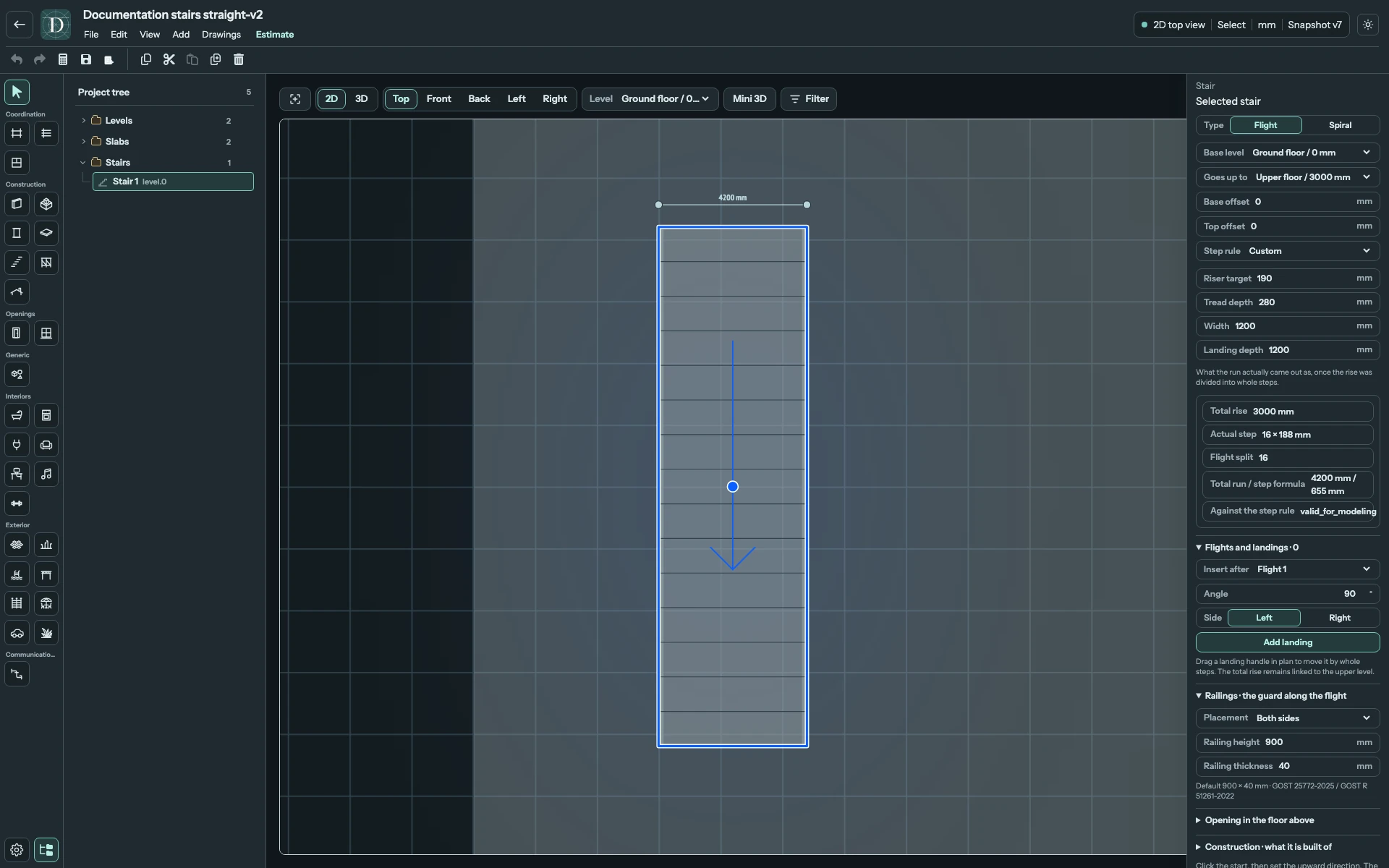
View the straight plan at full size.
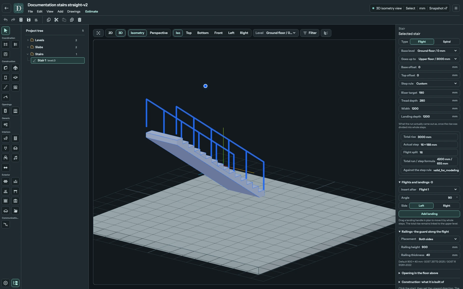
View the straight Stair in 3D at full size.
Landings and turns: 90°, 180° or another angle
Select the Flight and expand Flights and landings. These controls appear after creation; Spiral has no Flight landings.
| Control | Use |
|---|---|
| Insert after | Choose the run after which to add the new landing. |
| New Angle | Turn magnitude from 5° to 180°. Use 90° for a quarter turn, 180° for a return or another angle for your layout. |
| New Side | Left or Right, following the upward route. |
| Add landing | Adds one landing using the selected run, angle and side. Pressing Enter in the new Angle field also adds a landing; use either action once. |
| Existing landing angle and side | Edit that individual turn. This rebuilds it and the downstream route. |
| Remove | Removes that landing and rebuilds the remaining runs. |
Each example below has one Right turn after Flight 1. The new-landing fields can still show their initial 90°/Left values; the existing row below Add landing shows the turn already in the Stair.
Quarter turn: 90°
Set the new Angle to 90°, choose the side, then add the landing. Top makes the direction change clear; 3D shows the two runs at different elevations.
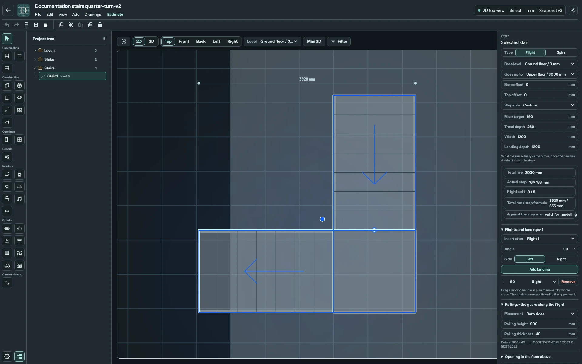
View the 90° plan at full size.
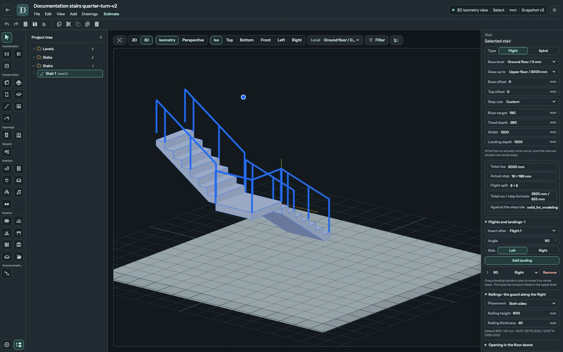
View the 90° Stair in 3D at full size.
Return: 180°
Set Angle to 180° and add the landing. The runs return alongside one another; the landing spans their direction change.
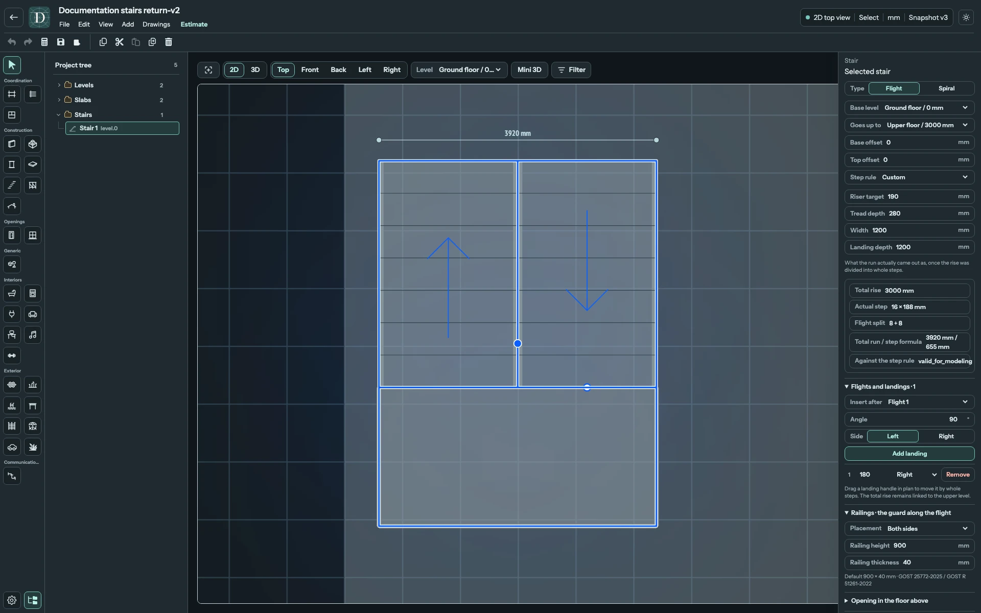
View the return plan at full size.
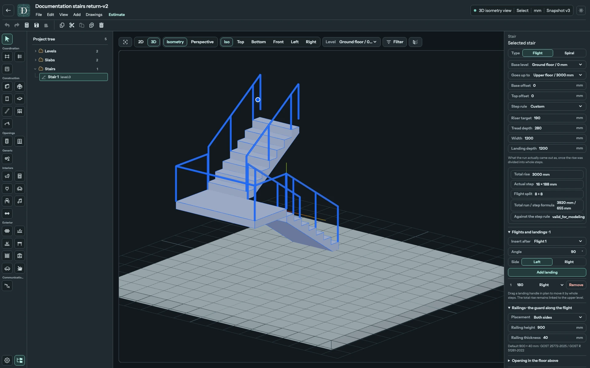
View the return Stair in 3D at full size.
Custom angle: 120° example
Enter the angle your route needs, within 5°–180°. A 120° turn is shown here; it uses the same controls as the right-angle examples.
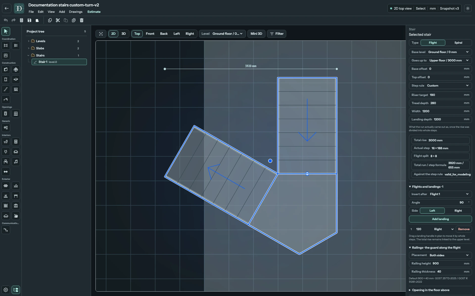
View the custom-angle plan at full size.
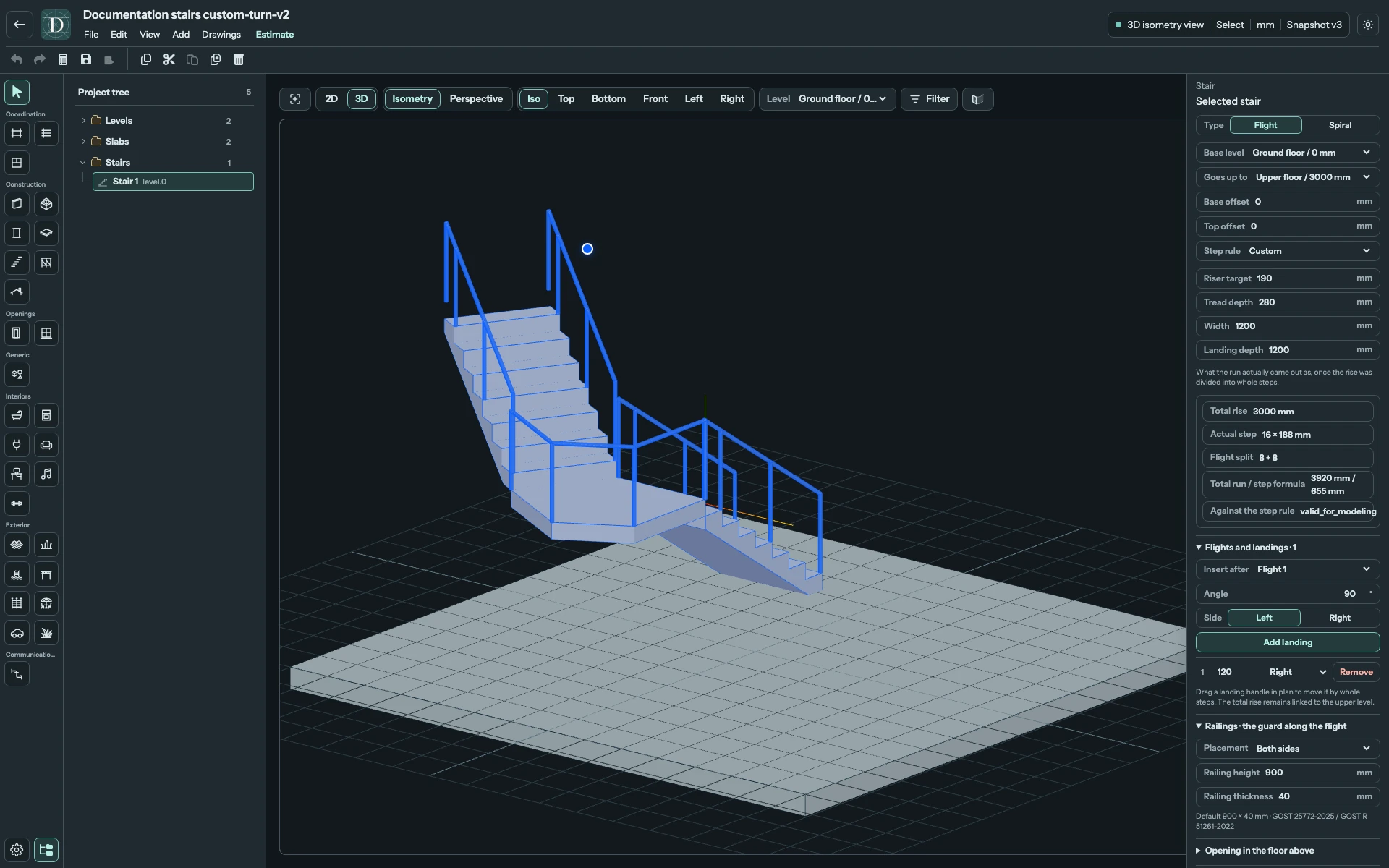
View the custom-angle Stair in 3D at full size.
Add further landings after the appropriate runs when needed. Drag a landing handle in Top to move its division by whole steps. The total rise remains connected to the upper elevation; the riser allocation and run lengths change. Check the rebuilt route and upper-floor opening after moving a landing.
Spiral: radius, ascent and central column
Choose Spiral, then set Inner radius, Radial step width and Depth at walking line. The example uses a 350 mm inner radius and 1000 mm radial width, giving a 1350 mm outer radius. The center is an imaginary placement reference until you enable Central column.
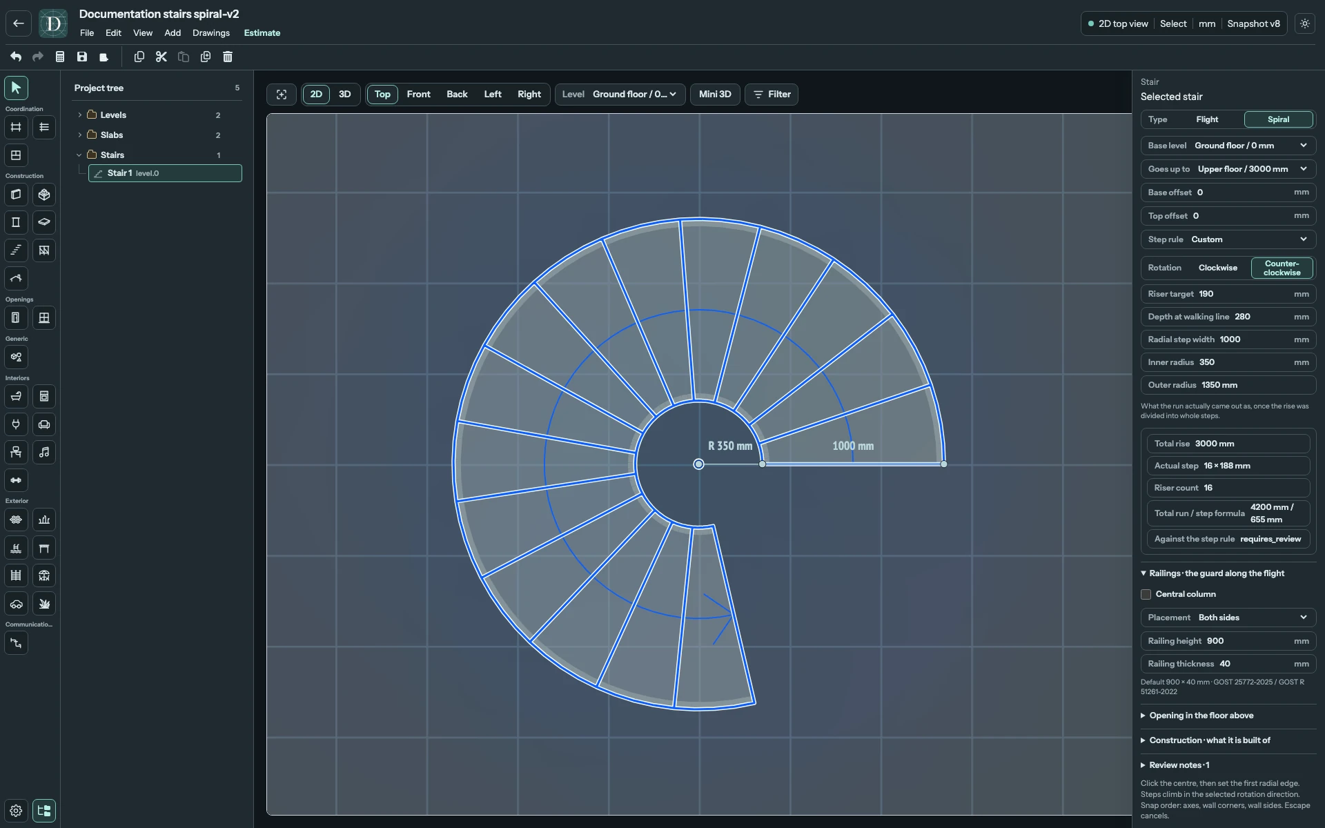
View the Spiral plan at full size.
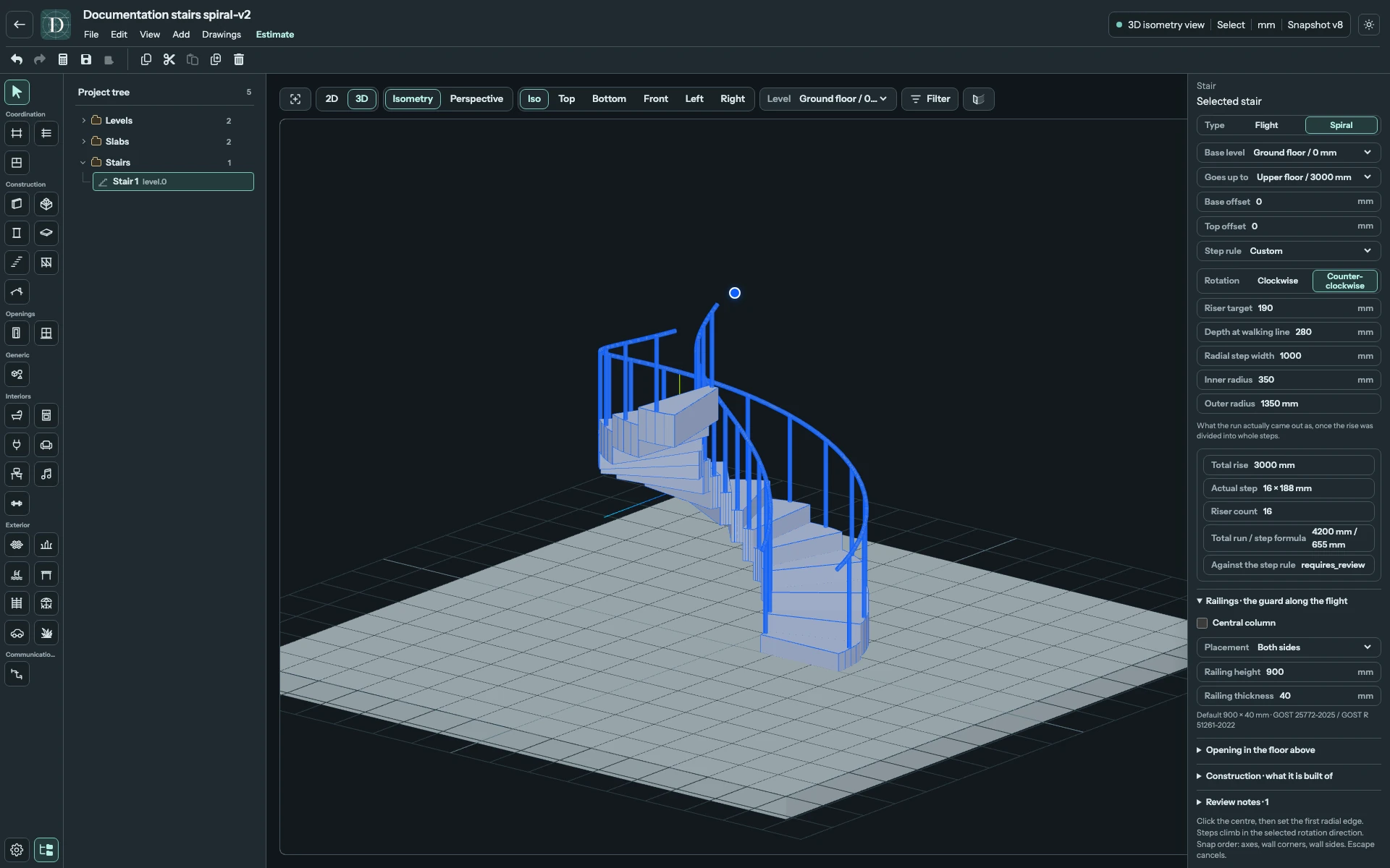
View the Spiral without a central column at full size.
Under Railings · the guard along the flight, enable Central column to fill the inner radius with a solid column from the base to the Stair top. Its diameter is twice Inner radius, its height follows Total rise and its material follows the Stair. It replaces the inner railing while preserving the outer railing choice. Disable it to restore the requested inner railing.
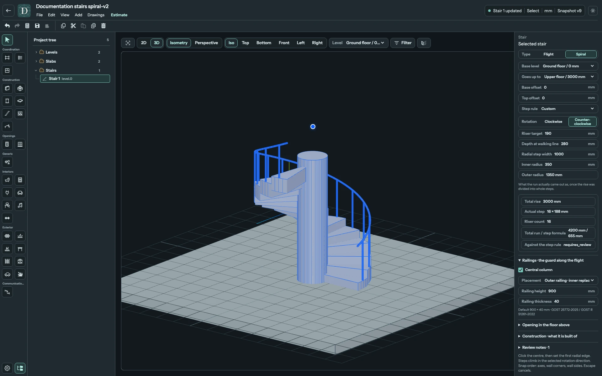
View the Spiral with a central column at full size.
Changing Rotation mirrors the direction of ascent around the first radial edge. Inspect the start and upper arrival after switching; a suitable footprint alone does not prove that the arrival fits the building.
Railings and construction
| Setting | Effect and choices |
|---|---|
| Placement | Flight: Both sides, Left side, Right side or No railings, following ascent. Spiral: Both sides, Inner railing, Outer railing or No railings. With Central column enabled, the inner choice is marked as replaced and Both sides displays Outer railing · inner replaced. |
| Railing height | Height above the Stair route, at least 100 mm. Default 900 mm. |
| Railing thickness | Thickness of the modeled guard members, at least 5 mm. Default 40 mm. |
| Central column | Spiral only; fills the inner radius and replaces the inner railing as shown above. |
| Construction | Under Construction · what it is built of: Monolithic reinforced concrete or Welded steel · individual treads. Rebuilds the modeled assembly. |
| Material | Choose a material compatible with Construction. Incompatible options are disabled; a persisted incompatible assignment has a warning asking for a compatible material. |
The numerical limits are input limits; they do not establish an appropriate guard for a particular project. These railings are part of the Stair. The independent Railings tool creates a separate element.
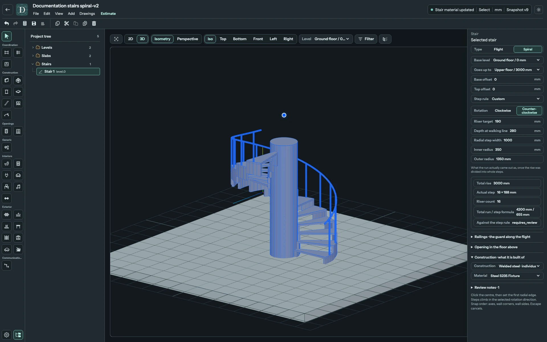
View the steel Spiral at full size.
Create and check the upper-floor opening
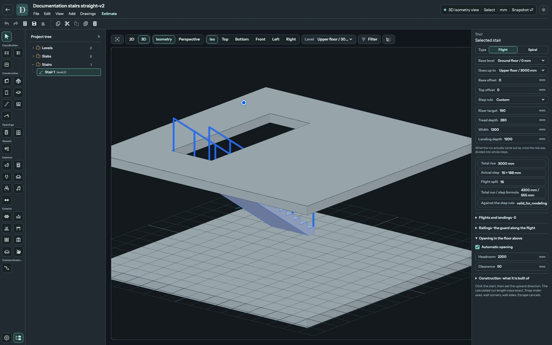
Expand Opening in the floor above. The Stair can generate its own linked hole in a compatible Floor Slab.
| Setting | Effect and limit |
|---|---|
| Automatic opening | Generate or rebuild the Stair's linked upper-Slab hole. Disabling it removes that generated hole; manual Slab holes remain separate. |
| Headroom | Vertical clearance used to locate the required opening along the route, at least 1000 mm. |
| Clearance | Additional plan allowance around the generated opening, at least 0 mm. |
A connected Stair needs one unambiguous compatible upper Slab and a valid opening inside it. The generated hole must avoid invalid intersections and overlapping holes. If no suitable host exists or the result is invalid, the Stair remains visible and Review notes explain the unresolved opening. Checking the box alone does not prove that a hole exists.
The linked hole follows changes to the Stair and its placement. For a Flight, the opening begins where the supplied headroom would otherwise be lost and continues to the top arrival; a Spiral uses a circular opening around its outer radius with Clearance.
View the upper-floor opening at full size.
Move, rotate, remove and reopen
Use the selected Stair's handles in Top or Main 3D to move or rotate it. Rotation uses the footprint's center; the first step can move during rotation. Rise, step count and elevations remain unchanged, while the route and generated opening rebuild at the new placement. See Move and reshape for the shared controls.
Select the Stair and press Delete, or use the editor's Delete action, to remove it. Its generated floor opening is removed with it; independent manual holes remain. Undo restores the edit. Copy, paste and duplicate create another Stair with its own identity and generated opening, subject to valid placement and hosting.
Use Save, then reopen the project. Select the Stair and check its type, Base level, top connection, dimensions, turn rows, railings, Construction and opening. Check the upper-floor view as well as the lower-floor route.
Drawings and estimates
A Spiral plan drawing shows its ascent arrow, step note, radial width and outer radius. The center is labeled by inner radius when open, or by column diameter with a cut hatch when Central column is enabled. Elevations show the total rise and a callout above the railings. Check the view, scale and surrounding annotations in the drawing.
An estimate counts the Stair, its central column and remaining railings as one finished Stair priced per item. The central column contributes to Stair material quantity and creates no separate Column row. Recalculate after changing dimensions, construction or the column choice.