
A Railing creates a barrier assembly along a route. Use it for a balcony, terrace or platform edge. It has its own Level and height; it is separate from a Stair's built-in railing settings.
Draw a route along an edge
- Open 2D → Top and choose Railing under Construction.
- Set Type, Height, Maximum module width, Level and Base offset.
- Choose the drawing direction and segment-length controls described below. Click the start and successive route points. Follow the edge you want to enclose, leaving the intended access side open.
- Press Enter or Esc, double-click or right-click to finish an open route. Clicking the first point again creates a closed route when valid.
An open route needs at least two distinct points; a closed route needs at least three. Segments must have nonzero length and the route must not cross itself. Select the result in the viewport or under Railings in the tree. Backspace removes the latest point while a route is still being drawn. Esc finishes a valid open route, so use Backspace to remove unfinished points when you want to abandon it without creating a Railing. With only one point, Esc abandons the unfinished route.
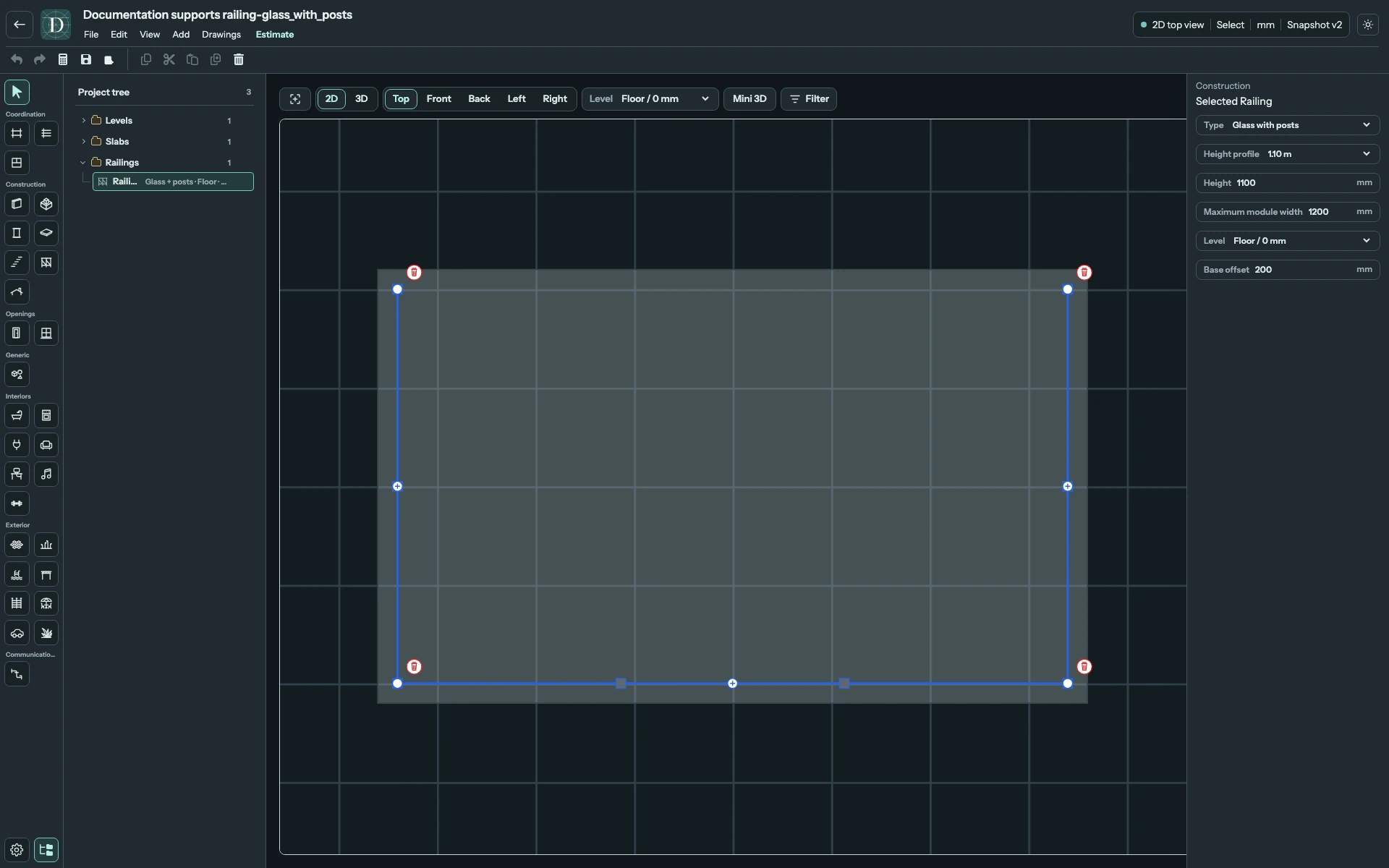
View the full-size screenshot.
Drawing direction and segment length
While the Railing tool is active, the viewport drawing toolbar provides:
| Control | Effect while drawing |
|---|---|
| Free / 90° | Free permits different directions. 90° constrains the next segment horizontally or vertically from the last point. |
| Length → Free / Step | Free permits an arbitrary segment length. Step rounds the length to multiples of the entered step. |
| Railing segment length step | Enabled in Step mode. Enter a positive increment in the displayed project unit, then press Enter or leave the field. The minimum is 1 mm, 0.1 cm or 0.01 m, depending on the project unit. Invalid values retain the previous step; Esc in this input restores the previous entry. |
These controls apply to the next authored segment. They do not reshape an existing route or set the assembly's Maximum module width. A physical snap can take precedence over a drawing constraint; check the preview and resulting endpoint.
Compare the four infills
All four types use the same route and primary controls. Changing Type rebuilds the assembly without changing the route.
| Type | Modeled components |
|---|---|
| Glass with posts | Transparent panels separated by posts and horizontal rails. |
| Frameless glass | Transparent panels supported by a continuous base shoe, without vertical posts. |
| Metal vertical balusters | Posts and rails with repeated vertical infill members. |
| Timber cross-brace | Posts and rails with diagonal cross-bracing. |
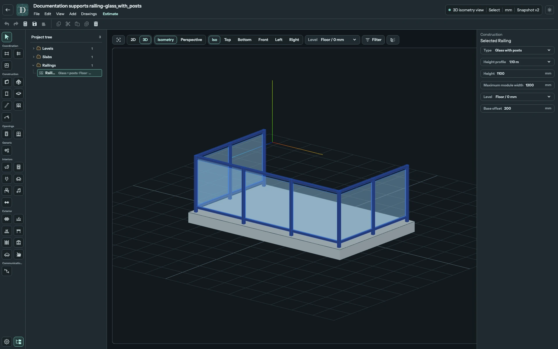
View the full-size screenshot.
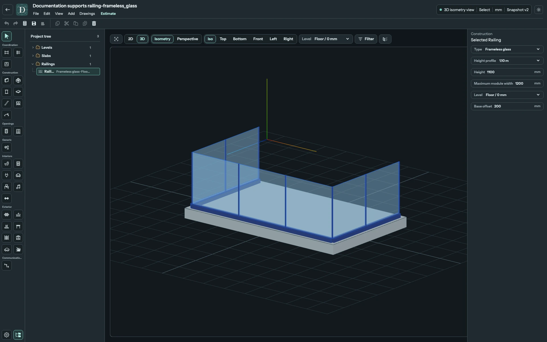
View the full-size screenshot.
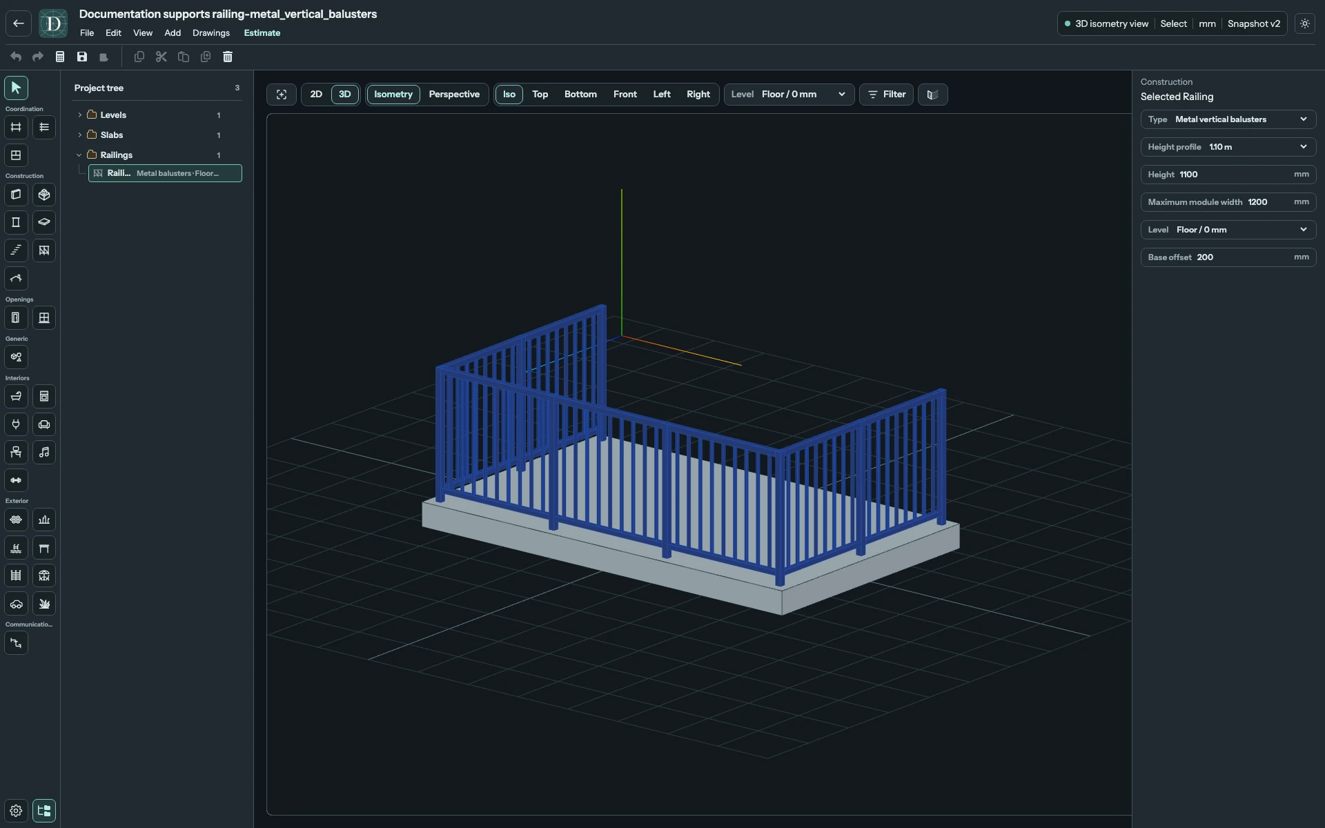
View the full-size screenshot.
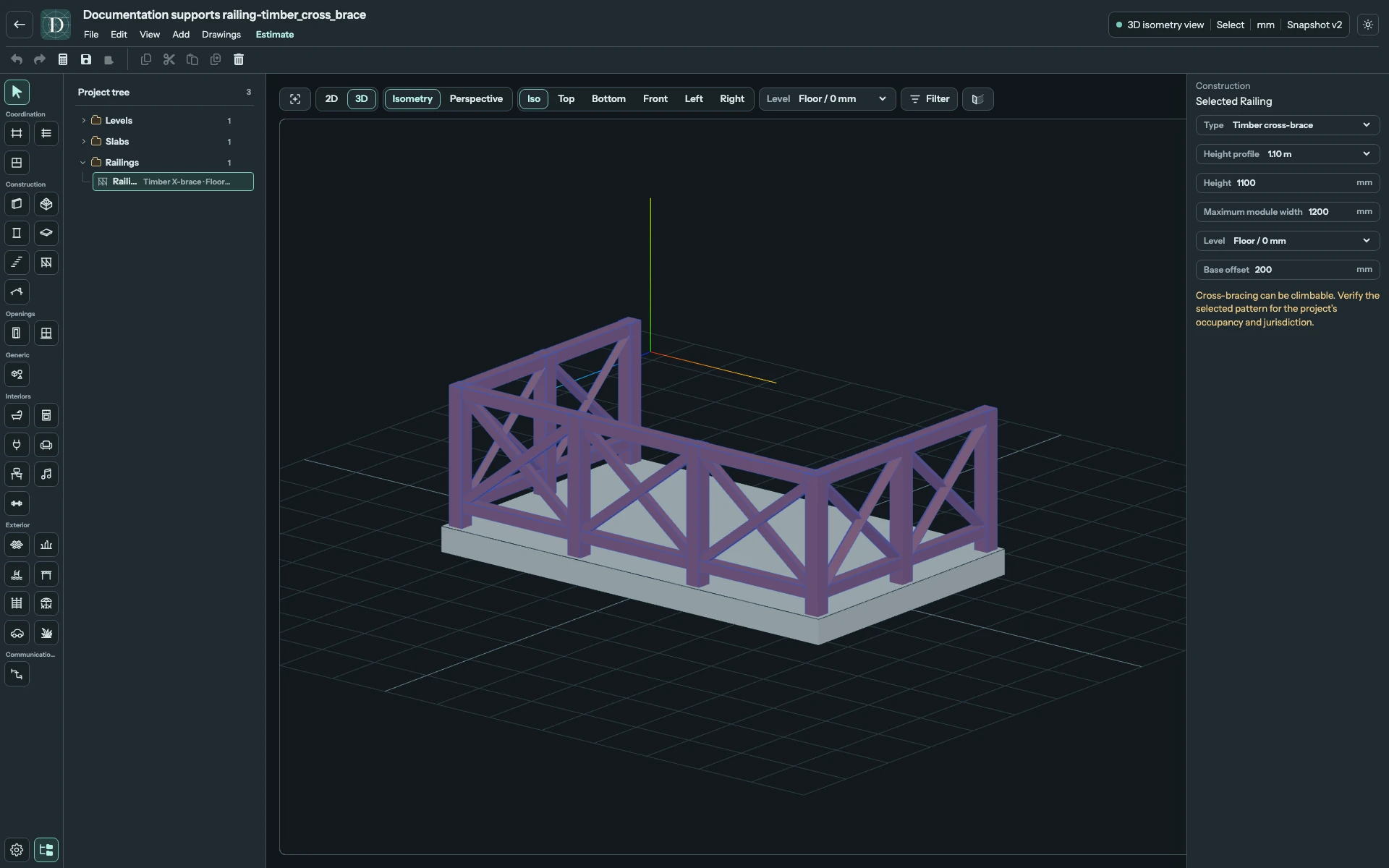
View the full-size screenshot.
Adjust every route and assembly setting
| Setting | Meaning and effect |
|---|---|
| Type | One of the four assemblies above. |
| Height profile | 0.90 m, 1.10 m or 1.20 m sets Height to that value. Custom represents another authored height; choosing Custom alone does not choose a new numeric height. |
| Height | Positive vertical distance from the Railing base to its top. Enter the project length unit shown beside the field. |
| Maximum module width | Positive upper span limit for repeated panels or post bays. It is not total route length and does not prescribe each infill member's spacing. |
| Level | Datum for the Railing base. |
| Base offset | Signed distance from that Level to the whole assembly base. Positive raises it, negative lowers it. |
The example Floor has its top at 200 mm above Level 0. The Railing uses that Level with Base offset 200 mm to meet its top. Moving the Floor does not automatically move this independent Railing, so check both datums after an edit.
Reduce Maximum module width from 1200 to 800 mm on the same route to add smaller bays. Dravit subdivides each straight span and adapts the end bays; inspect corners and short spans in 3D.
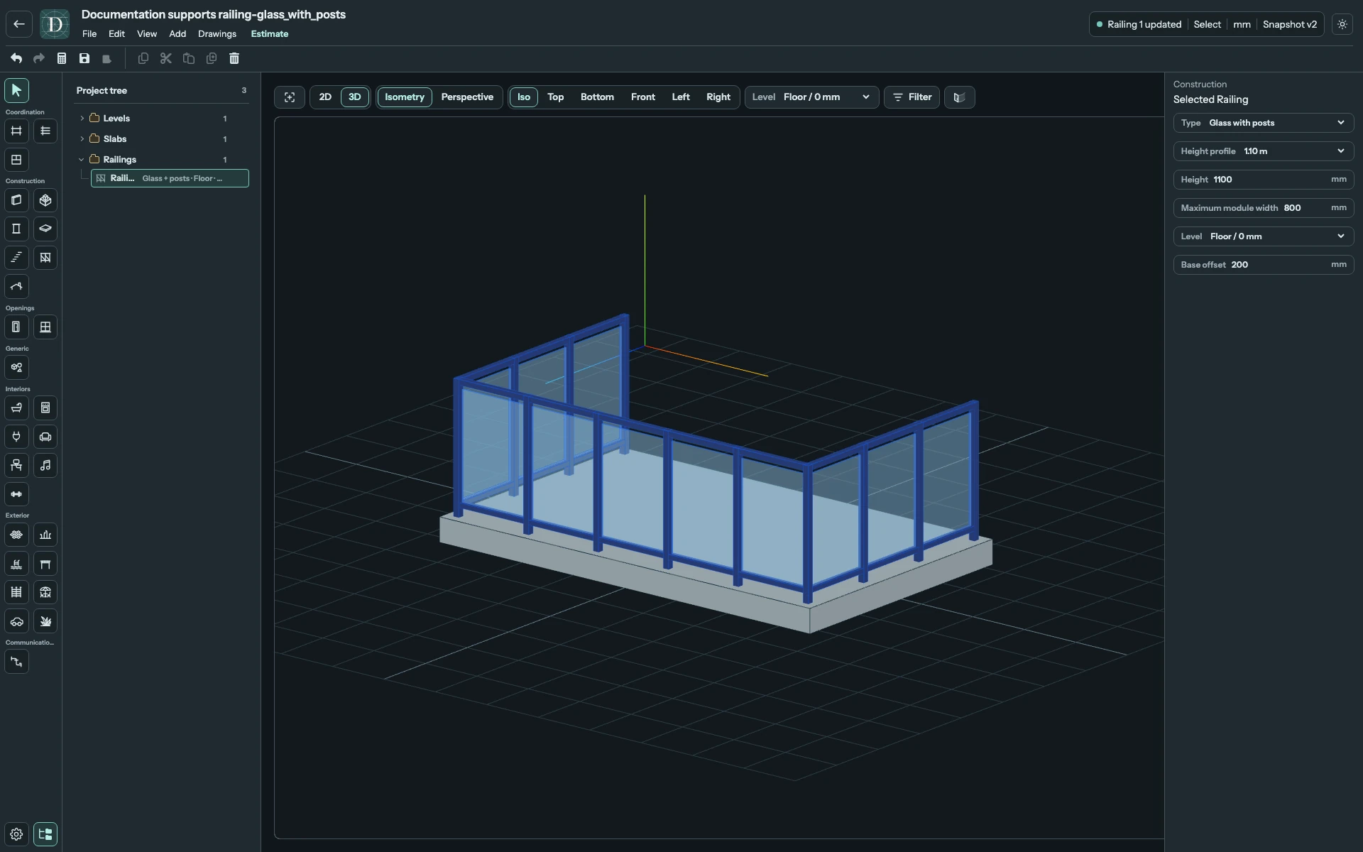
View the full-size screenshot.
These height profiles are modeling choices. The assembly does not verify infill strength, anchorage or requirements for a particular occupancy. For Timber cross-brace, review the climbable pattern identified by the panel.
Reshape or remove the Railing
In Top, drag a route vertex to move that corner. Use the + on a span to insert a point and the red deletion control to remove a point. Removing a point joins its neighbours, so inspect the new segment. Deleting a vertex when only two points remain in an open route, or three in a closed route, deletes the whole Railing. The Railing has no whole-object move grip; reposition its route vertices individually.
The selected Railing panel currently has no instance Name field, editable point count or Open/Closed switch. The route is determined by its authored points and the way it was finished. Use the route controls above to change its shape.
Check the base in a side view and the modules in 3D, then Save and reopen. Use Delete on the selection to remove the entire Railing. Undo restores an accidental edit or deletion.