
A Wall is a physical building element with a straight baseline, thickness and vertical extent. Use it to model an enclosure or partition and to host Doors and Windows. Its baseline is the line you draw; Draw by determines whether that line represents the center or one face of the Wall.
Draw a Wall chain
- Open 2D → Top and choose the building Level you want to work on. Select Wall under Construction, or press W.
- In the right panel, choose Wall type, Level, Draw by, Base offset and Top elevation. Thickness comes from the type. Use Wall types when the required construction is missing.
- Click the first endpoint, then the next endpoint. Each following click adds another straight segment. Follow the preview and snap marker when using an Axis or existing geometry.
- Press Esc to end the chain. Return to Select and inspect the Walls in the plan or Project tree.
Use Center when your construction Axis should pass through the center of the Wall section. Left and Right place a face on the drawn line, relative to the direction from the start to the end. These are alignment choices, not labels for the building's inside and outside. Inspect the preview before placing the segment.
Direction Free/90° and Length → Free/Step constrain each new segment independently. For a 100 mm increment, choose Step and enter 100 mm before placing its endpoint. See direction and length controls for examples and the difference from snapping or permanent bindings.
Reshape an existing Wall
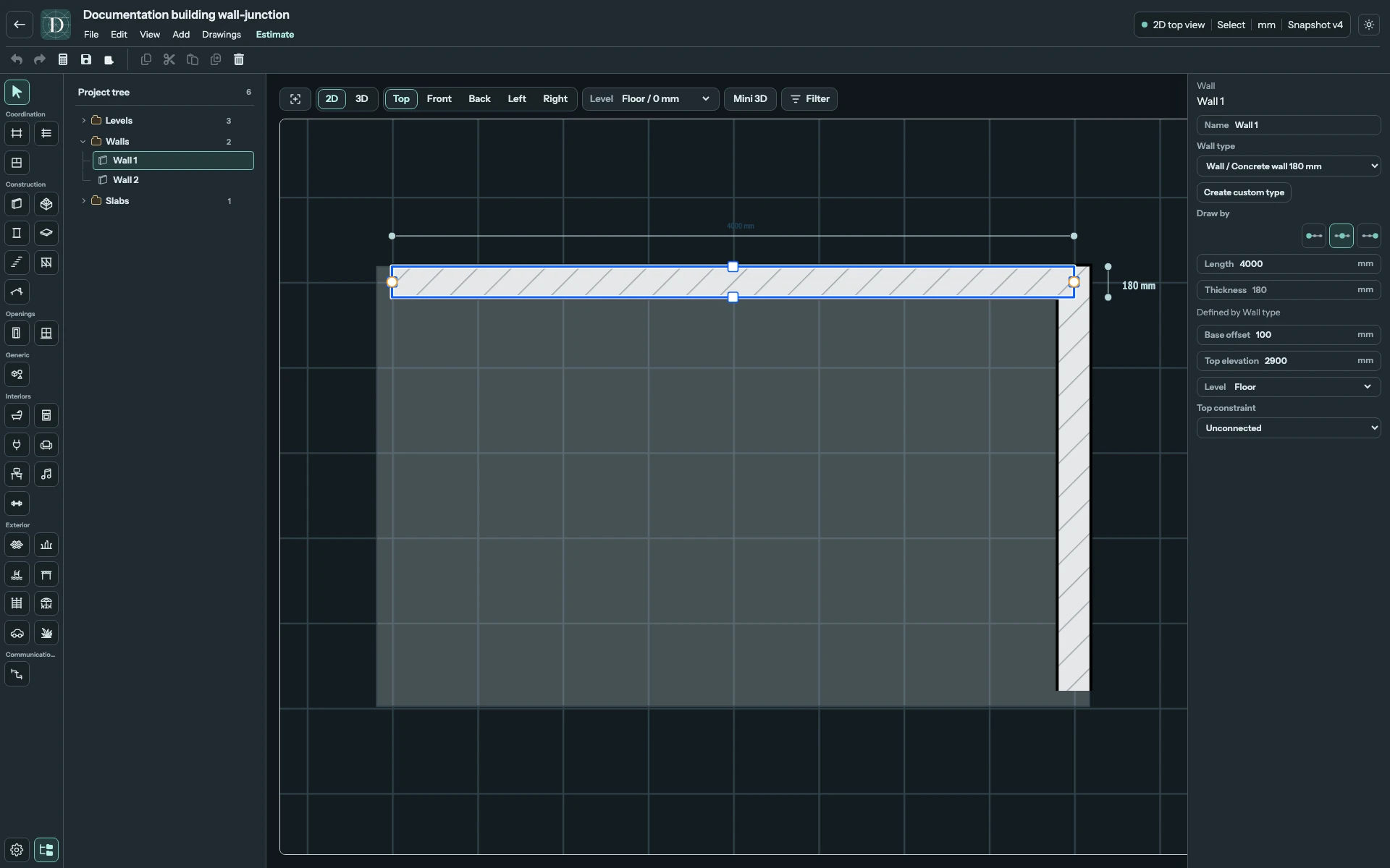
Select the Wall in Top. Drag either baseline endpoint to change that end. The other endpoint stays in place. For an exact length of at least 80 mm, enter Length in the inspector; the Wall keeps its start point and direction while its end changes. There is no whole-Wall move grip: reposition the baseline endpoints individually, then check its length and direction. Move and reshape compares the controls available to different families.
View the full-size screenshot.
Changing Draw by keeps the baseline and changes where the thickness lies around it. Walls with meeting endpoints can form a joined outline. Editing one Wall's endpoint does not give it ownership of its neighbour: check the junction after reshaping. Hosted Doors and Windows keep their relationship with the edited Wall; check their resulting positions and the opening diagnostics.
For one Wall, edit Name to label it in the Project tree, using up to 255 characters. With several Walls selected, the inspector shows shared values or Mixed values; choosing a shared type, alignment, Level or vertical value applies it to the set. Individual Length and Top constraint editing are disabled for multiple Walls, and Name is only offered for one Wall. See multiple selection for Ctrl/Command and rectangle selection.
Set the Wall base and top
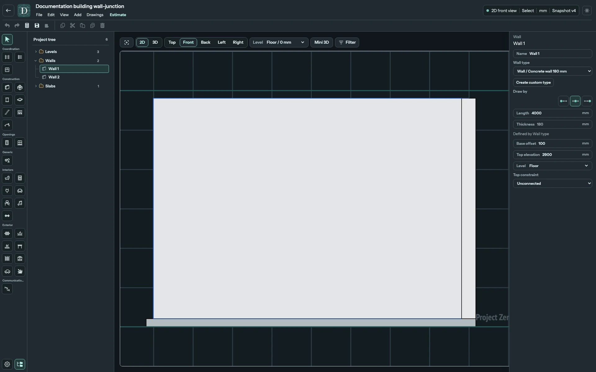
Both vertical fields are measured from the selected Level, not from project zero:
| Setting | Meaning |
|---|---|
| Level | The Wall's base datum. |
| Base offset | The signed distance from that Level to the Wall bottom. Positive raises the bottom; negative lowers it. |
| Top elevation | The Wall top measured from the same Level. It is not a height measured from the Wall bottom. |
| Thickness | Read-only here. Change the Wall type to change it. |
View the full-size screenshot.
For an Unconnected Wall, height is Top elevation minus Base offset. For example, with a Level at 0, a base offset of 100 mm and top elevation of 2900 mm make a 2800 mm high Wall. These numbers illustrate the relation; use dimensions chosen for your design. Dravit requires at least 200 mm of physical Wall height.
For a selected Wall, choose Top constraint:
- Automatic next Level follows the next higher Level. With no upper Level available, the panel reports that the default top elevation is active.
- Automatic Roof underside derives the top profile from a compatible Roof. The scalar field becomes Fallback top elevation. Use side views and 3D to inspect the actual sloping cut, rather than reading the fallback as the resolved height.
- Unconnected uses your authored top elevation.
Entering a new top elevation releases an automatic top relation. Editing a roof-bound fallback can affect the attachment of the joined Wall network. A roof attachment needs compatible geometry; conflicting Roof attachments on joined Walls can block an edit and report an error. Read the status message before assuming the change succeeded.
View the full-size screenshot.
Check the result
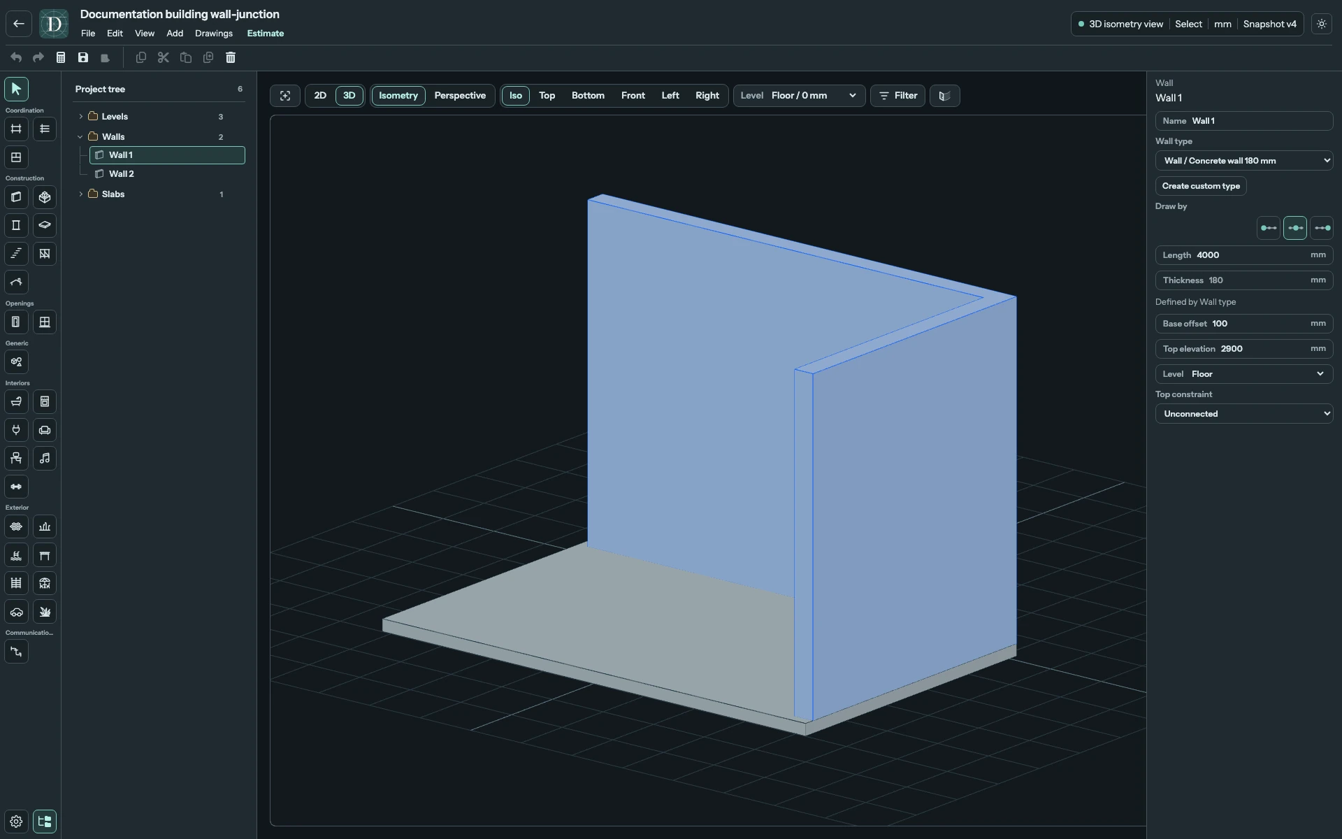
Inspect the Wall in Top, a suitable side view and 3D. Top shows the footprint but cannot prove a vertical edit. Verify the junctions, base, top and hosted openings, then Save and reopen the project. A Roof-owned generated wall closure is a separate derived component; use an authored Wall when you need a Door or Window host.
Use Delete on a selected authored Wall to remove it. Check its hosted openings and the remaining junctions; Undo restores an accidental deletion.