
Pavement creates a flat paved or asphalt area with a closed boundary and thickness. Its optional Kerb follows the edges you enable and remains part of that pavement. Use Top to draw and round the boundary; use 3D to inspect thickness, kerb height and neighboring surfaces.
Paving and asphalt
| Type | Starting Material | Starting Assembly | Starting Thickness |
|---|---|---|---|
| Paving | Concrete Paver Preliminary | Concrete block paving | 80 mm |
| Asphalt | Asphalt Preliminary | Single-layer asphalt | 70 mm |
Changing Type alone preserves the existing Material, Assembly and Thickness. Choose Apply preset to replace those three fields with the selected type's starting values. It preserves the boundary, elevation, corner radii and kerb settings. Review those construction fields before applying a preset to a customized area.
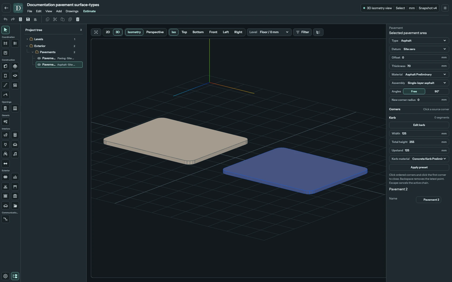
View the two surface types at full size.
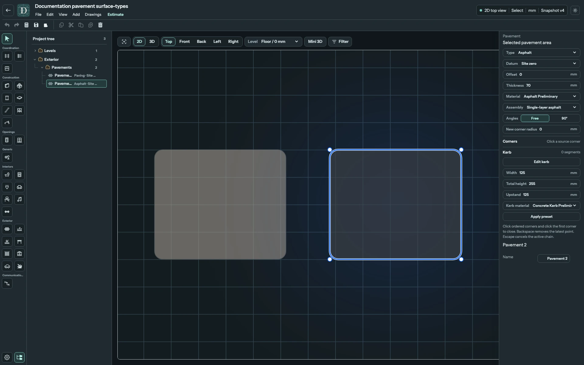
View the two footprints at full size.
Draw a pavement area
- Choose 2D → Top, then Exterior → Pavement.
- Choose Type, Datum, Thickness, Material and Assembly. Use Apply preset if you want that type's starting construction settings.
- Choose Angles → Free or 90°. New corner radius sets the radius applied to newly drawn corners.
- Click ordered corners and click the first to close the polygon. Backspace removes the latest draft point; Escape cancels the unfinished chain.
- Choose Select, then select the pavement in the viewport or Exterior → Pavements in the Project tree.
Every area control
| Control | Effect and conditions |
|---|---|
| Name | Renames the selected area in the object inspector below its pavement settings. |
| Type | Paving or Asphalt. Switching it does not apply a preset automatically. |
| Datum → Site zero | The area's bottom is at the site-zero elevation plus Offset. The object belongs to the Site. |
| Datum → Level | Reveals Level and Offset. The area's bottom follows that Level's elevation plus Offset; it uses building-storey ownership. |
| Datum → Absolute elevation | Reveals Elevation in place of Level/Offset. Enter the area's bottom elevation directly; it uses building-storey ownership. |
| Level | Existing reference Level, available for the Level datum. |
| Offset | Signed distance from Site zero or the selected Level. |
| Elevation | Signed absolute bottom elevation, available for Absolute elevation. |
| Thickness | Positive thickness extending upward from the area's bottom. Zero is not accepted. |
| Material | Selected pavement material. The current built-ins are Concrete Paver Preliminary and Asphalt Preliminary. |
| Assembly | Concrete block paving or Single-layer asphalt. This selects the available assembly rather than opening a layer editor. |
| Angles → Free / 90° | Direction constraint when drawing a new boundary; it does not straighten an existing area. |
| New corner radius | Nonnegative radius for future source corners. It does not replace radii on an existing boundary. |
| Apply preset | Replaces Material, Assembly and Thickness with the selected Type's starting values. |
Enter lengths in the displayed project unit. The surface remains horizontal: its datum moves the whole area, and corner X/Y settings do not create a slope. The Project tree groups all pavement datums under Exterior → Pavements.
Round and reshape corners
Click a source corner in Top to show its settings. Drag that corner to reshape the boundary, or enter exact X and Y coordinates. Hover a straight boundary edge and click its plus control to insert another corner.
| Corner control | Effect and conditions |
|---|---|
| X / Y | Exact plan coordinates, shown when one corner is selected. |
| Radius | Nonnegative fillet radius for the selected corner or corners. Zero produces a sharp corner. The radius must fit the neighboring segments and their other fillets. |
| Sharp | Sets the selected corners' radii to zero. |
| Rounded | Uses New corner radius, or 200 mm when that default is zero, limited by the available neighboring edges. |
| Delete corner | Available for one selected corner. If fewer than three corners remain, it deletes the whole pavement; Undo restores it. |
Hold Ctrl or Command while clicking corners to add or remove them from the corner selection. Multiple corners share Radius, Sharp and Rounded; X/Y and Delete corner are available only for a single corner. If selected corners have different radii, the shared Radius field is blank until you enter a common value.
A selected rounded corner also has a radius handle. Drag it to change the fillet without moving its source corner. The corner handle remains at the source intersection, outside the visible rounded arc.
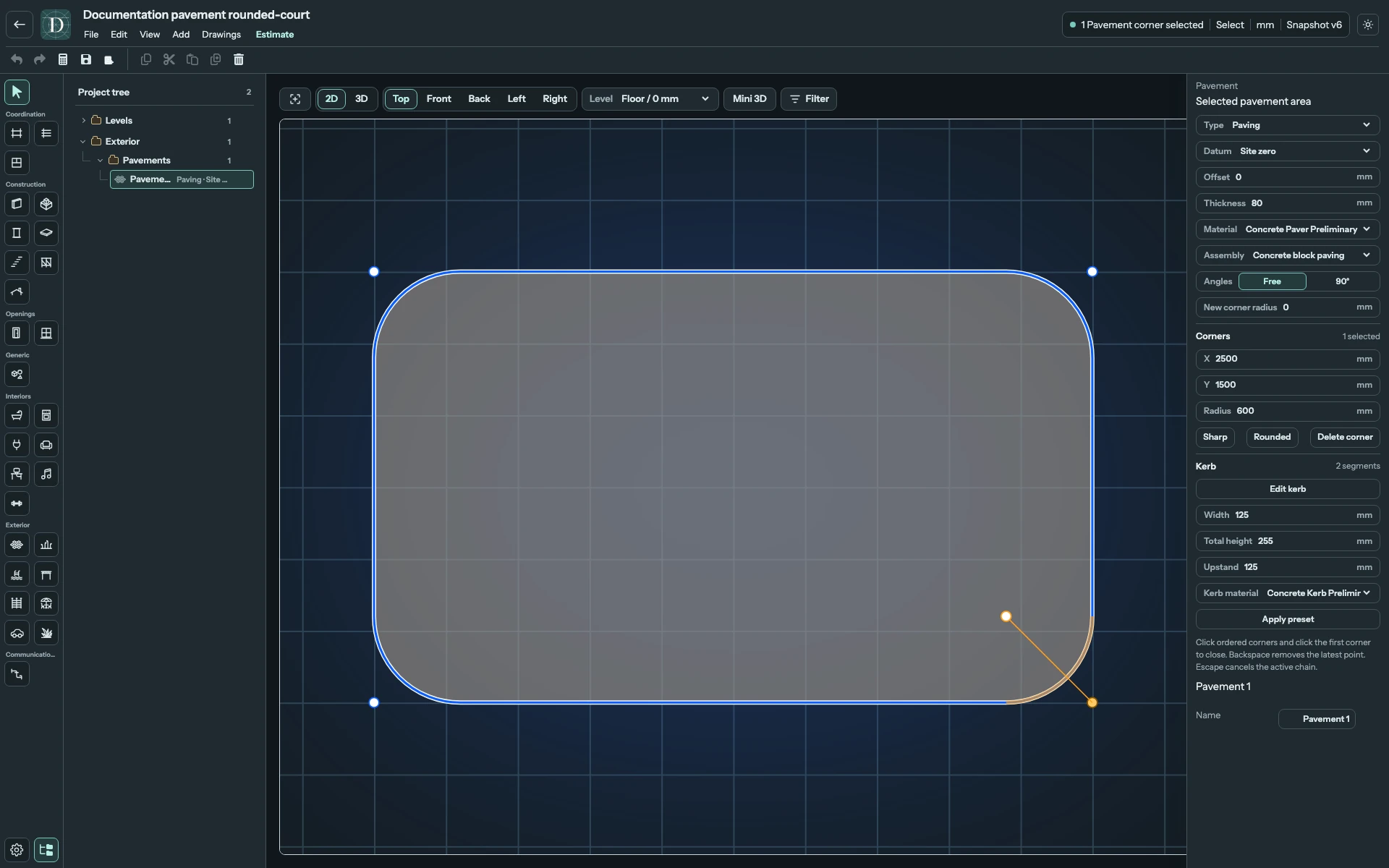
View the corner and radius controls at full size.
An impossible fillet or crossing boundary is rejected, retaining the previous valid geometry. An edit that leaves fewer than three corners or collapses the area to zero deletes the pavement. Use Undo to restore an accepted change or deletion, and Redo to reapply it.
Put kerbs on the required edges
- Select the pavement and choose Edit kerb. This switches to Top and clears the corner selection.
- Click a boundary segment to enable or disable its kerb. The segment count in the right panel reports how many are enabled.
- Use Whole perimeter to enable every segment or Clear perimeter to remove all runs.
- Set the kerb profile, then choose Done. Escape also leaves kerb-edit mode before deselecting the pavement.
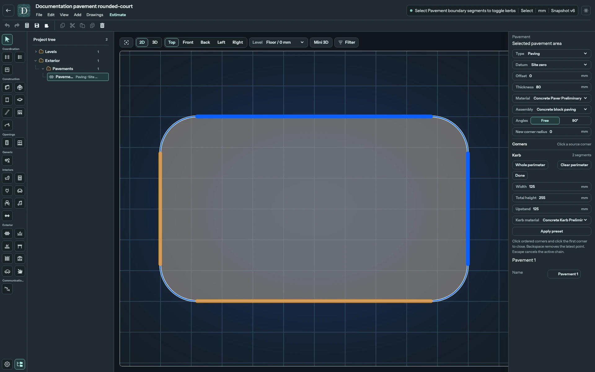
View kerb segment editing at full size.
| Kerb control | Effect and conditions |
|---|---|
| Width | Positive kerb width outside the pavement boundary. Starting value: 125 mm. |
| Total height | Positive complete kerb height, including its portion below the surface. Starting value: 255 mm. |
| Upstand | Height above the pavement top. It can be zero, but cannot exceed Total height. Starting value: 125 mm. |
| Kerb material | Material for the enabled kerb runs. The current built-in is Concrete Kerb Preliminary. |
The kerb top is at the pavement's bottom elevation plus Thickness plus Upstand. Its bottom is that kerb-top elevation minus Total height. Adjacent enabled segments join around a valid corner; a run ends where the next segment is disabled. Invalid profile dimensions or a kerb offset that cannot fit the boundary are rejected.
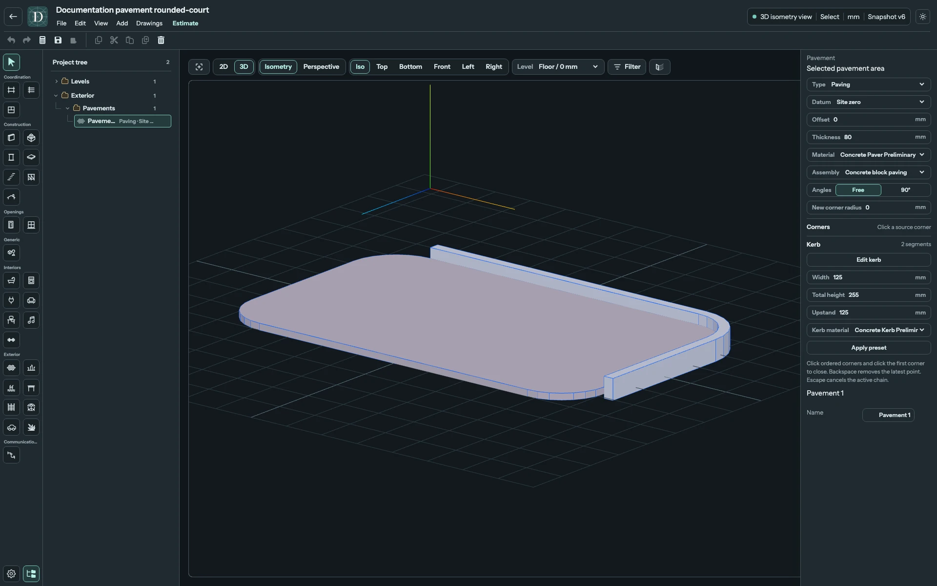
View the pavement and kerb assembly at full size.
Change elevation and retain the result
In this example, Asphalt uses Datum → Level, Floor / 0 mm, and Offset 300 mm. Its bottom rises 300 mm while the separate paving area remains at Site zero with Offset 0. Changing either surface's datum does not carry neighboring objects with it.
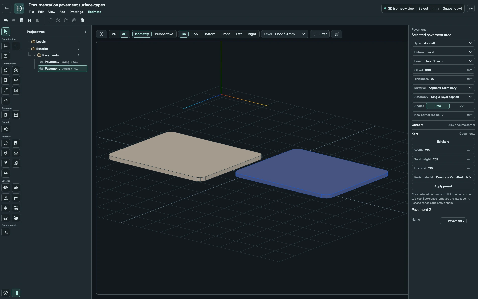
View the independent elevation change at full size.
The working Level in the viewport toolbar also limits what 3D displays. With Site zero or Absolute elevation, an area above that working Level can be hidden. Choose a working Level at or above its bottom elevation to inspect it. With the Level datum, visibility follows the area's bound Level. See Levels for the working-Level and display-filter controls.
Use Top for boundary editing and 3D for surface thickness and kerb heights. Pavement is omitted from architectural 2D side views. Delete the selected area with the editor's Delete action; Undo restores it. Save and reopen to retain the contour, radii, datum, construction fields and enabled kerb runs.
The presets are starting modeling values. Choosing an assembly does not provide a designed pavement build-up or verify the site's construction requirements.