
A Foundation is a concrete section extended along a straight baseline. Use a chain of segments to model a continuous foundation route. Its components stack upward from a bottom datum. A Wall above it and an optional Column pad are separate objects.
Compare the section families
Foundation type selects a built-in section or a reusable project type. These six built-in families have different components; they are not six names for the same section.
| Family | Modeled section and built-in example |
|---|---|
| T-shaped strip | A narrower Wall / stem above a continuous Footing. The example has a 250 × 900 mm stem and a 600 × 300 mm footing. |
| Strip footing | A footing without a stem, 600 × 300 mm in the example. |
| Foundation wall | A vertical 250 × 900 mm section without a modeled footing. |
| Trench fill | A full-width 500 × 900 mm concrete section, without a separate footing. |
| Ground beam | A linear 300 × 450 mm beam section. |
| Concrete blinding | A thin 700 × 50 mm working layer, without a stem or footing. |
The dimensions above are catalog examples. Choose your project's section; the tool does not size foundations from soil or structural loads.
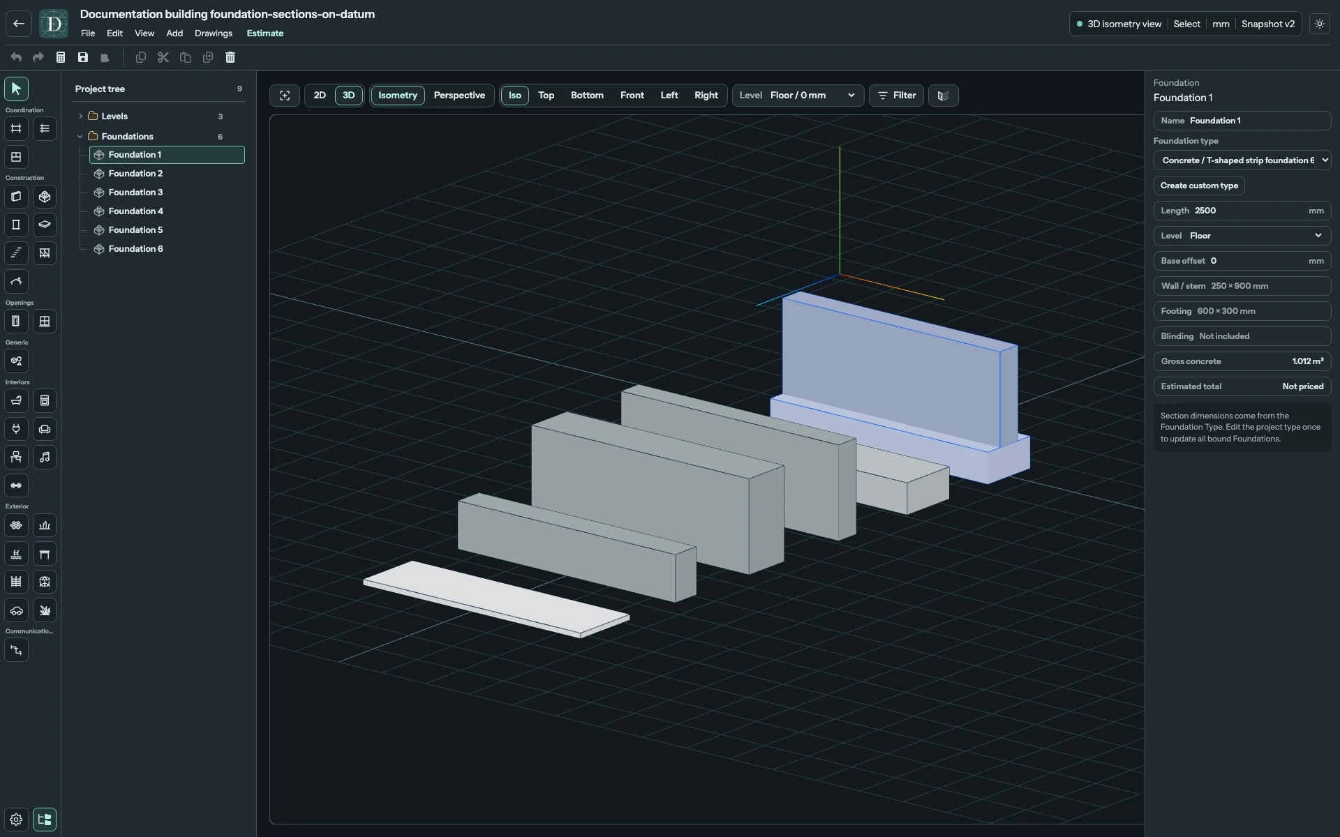
View the full-size screenshot.
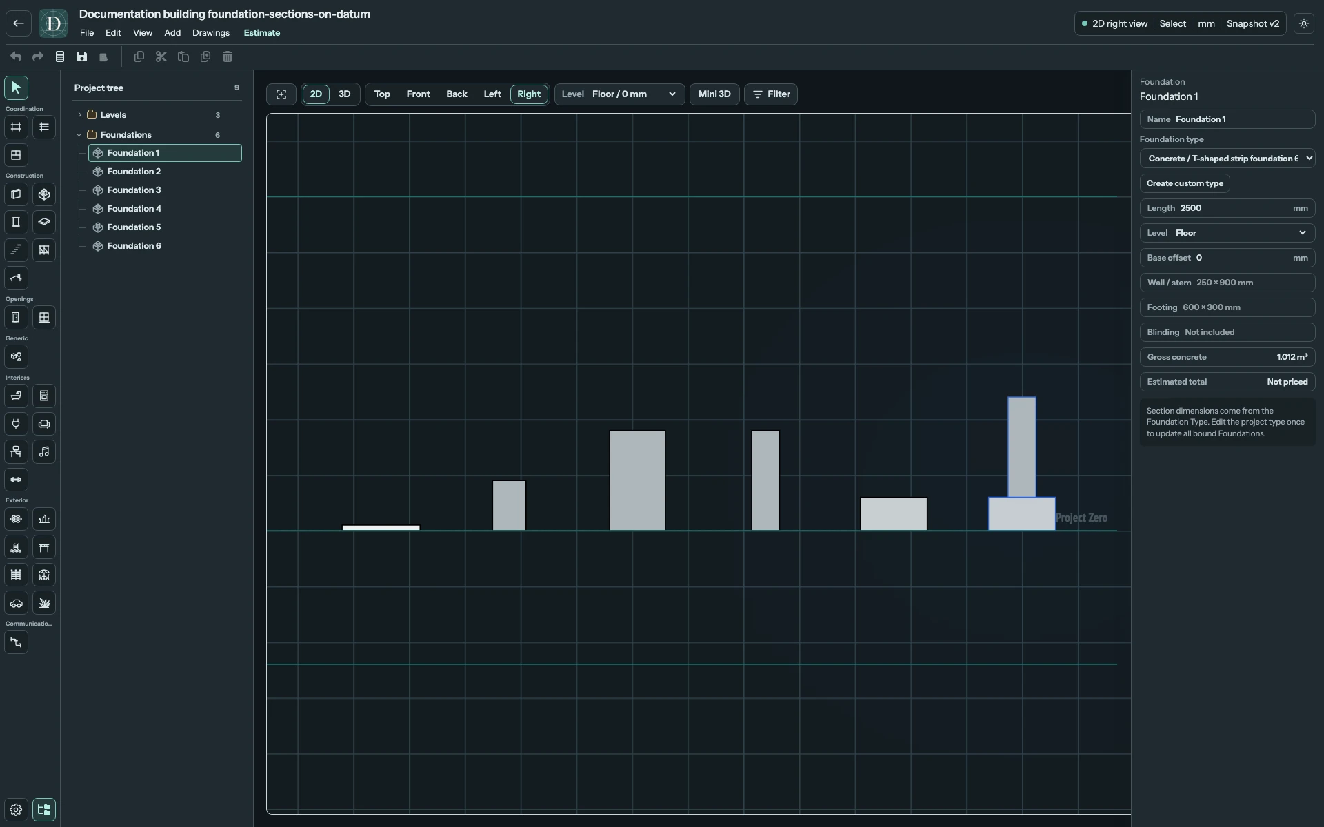
View the full-size screenshot.
Choose a datum and draw the route
- Open 2D → Top and choose Foundation under Construction, or press Shift+F. A building Level is required.
- If offered, choose Use negative Level, Create Foundation Level, or Continue on current Level. Depth below Level 0 is a positive downward distance from project zero when creating the negative datum.
- Choose Foundation type, Level, Draw by and Base offset.
- Click the first point, then successive endpoints. Each segment becomes a Foundation. Press Esc to finish the chain.
Draw by → Left/Center/Right places a face or center of the section on the baseline, relative to its start-to-end direction. Check the preview. Use Free/90° for direction and Length → Free/Step for length increments; they are separate from snapping.
Level is the bottom datum of the entire assembly. Positive Base offset raises it; negative lowers it. Components stack in this order: Blinding, Footing, Wall / stem, omitting components absent from the type. For example, a T strip with a 300 mm footing and 900 mm stem, no blinding, Level -1200 mm and zero offset reaches 0 mm at the stem's top. Adding 50 mm blinding raises that top to 50 mm unless you adjust the datum.
Inspect and edit a placed Foundation
Select a baseline in Top or an item under Foundations in the Project tree.
| Inspector field | Meaning and availability |
|---|---|
| Name | Selected instance label, up to 255 characters; offered for one object. |
| Foundation type | Changes the section for the selected instance or selection. |
| Create custom type | Defines a project section and assigns it to the selection. |
| Edit type | Offered for a selected project type; edits its shared definition. |
| Length | Baseline length; editable for one Foundation, at least 80 mm. |
| Level | Bottom datum; changing it moves the complete section vertically. |
| Base offset | Signed distance from that datum to the assembly bottom. |
| Wall / stem, Footing, Blinding | Read-only width × height from the type, or Not included. |
| Gross concrete | One object's modeled volume, including every present component. |
| Estimated total | One object's project-type price result, or Not priced; separate from the complete project estimate. |
With several Foundations selected, shared values are shown where possible; differing types, Levels or offsets show Mixed. A chosen type, Level or offset applies to the selection. Name, numeric Length and individual quantity/price summaries are available for a single object.
Drag baseline endpoints or edit Length to reshape the route. See move and reshape. Overlapping a Wall baseline does not bind that Wall to the Foundation. Inspect junctions and vertical positions in side views and 3D after an edit.
Define a reusable project section
Choose Create custom type. The dialog's fields depend on Section family.
| Dialog field | What to enter |
|---|---|
| Name / Description | Required, up to 120 and 500 characters respectively. Use a unique project type name; names differing only by letter case are duplicates. |
| Section family | One of the six families above; determines the component fields. |
| Concrete | Read-only Cast-in-place concrete. |
| Currency | Three uppercase letters; EUR is the initial value. |
| Wall / stem Width / Height | Positive dimensions for T-shaped strip and Foundation wall. The section is labeled Trench fill or Ground beam for those families. |
| Footing Width / Height | Positive dimensions for T-shaped strip and Strip footing. A T strip's footing must be at least as wide as its stem. |
| Concrete blinding | Optional lower layer for structural families. Always enabled for the Concrete blinding family, which has no other component. |
| Blinding Width / Height | Positive dimensions when enabled. Width must cover every component above it. |
| Complete supplied-and-installed price / m³ | One nonnegative finished-construction rate. Enter a positive rate when pricing the type. |
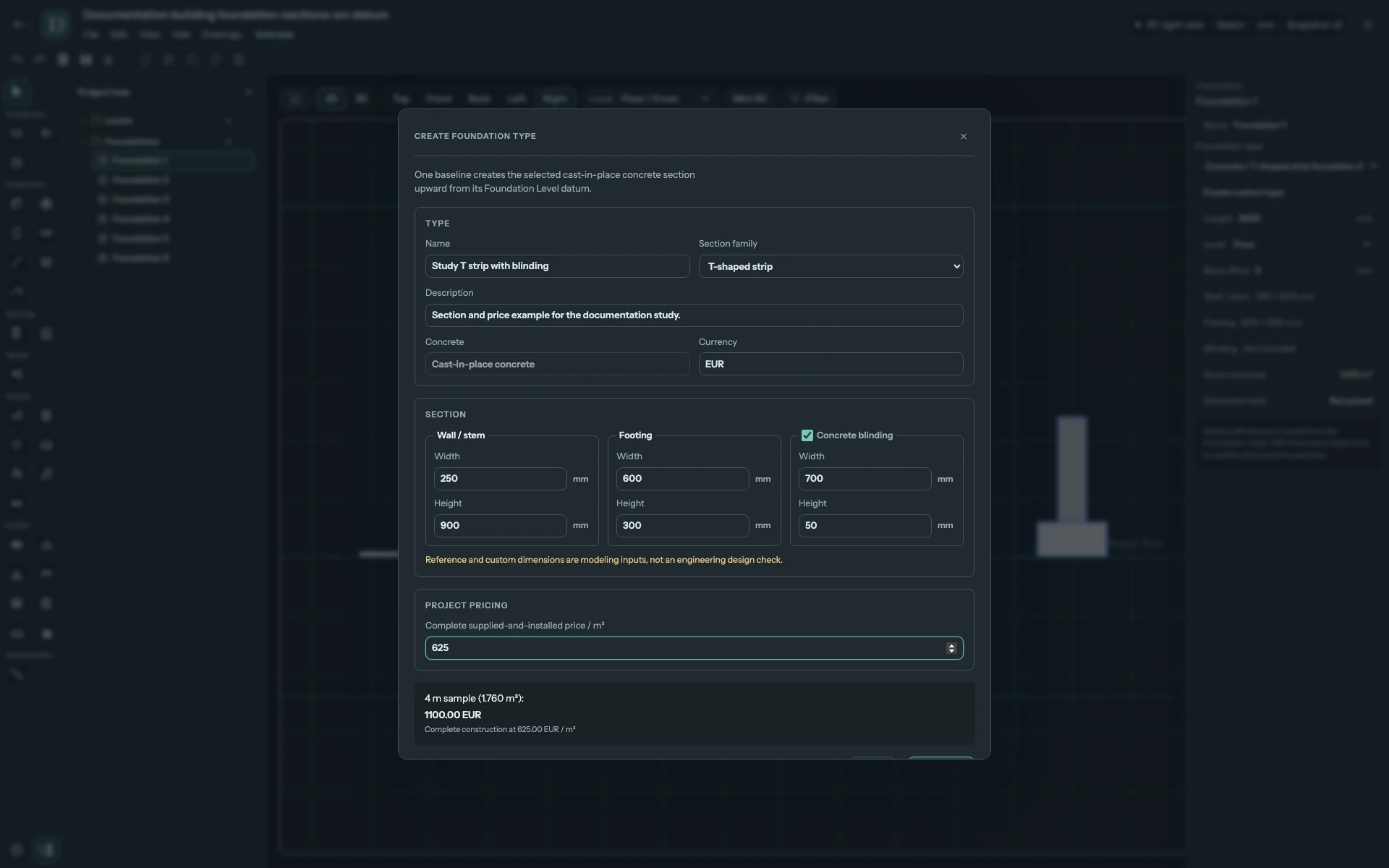
View the full-size screenshot.
The price includes applicable groundworks, preparation, formwork, reinforcement, concrete, work and logistics. A concrete-only rate is not a finished Foundation rate. The unit is m³, even though the geometry is drawn by length. The 4 m sample multiplies the sum of component cross-section areas by 4 m, then by your complete rate.
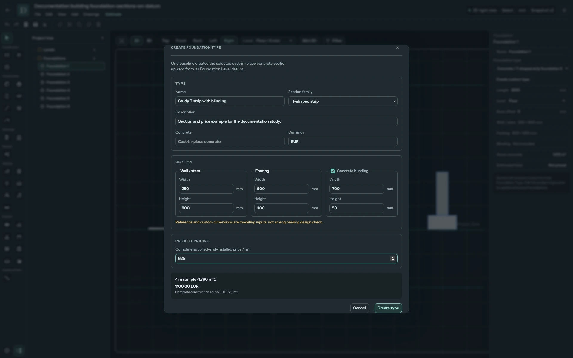
View the full-size screenshot.
Create type saves the project definition; Cancel closes without creating it. To change that definition later, select an instance using it, choose Edit type and Save type. All bound Foundations receive the new section. Their individual lengths, Levels and offsets remain unchanged. Check every affected junction and top elevation.
Place a Window in the stem
A Foundation with a Wall / stem component can host a Window. Work in Top on the Foundation's datum Level and place the Window on that component's face. Its width, height and sill must fit within the stem. Sill height is measured from the stem bottom, above any Footing and Concrete blinding, rather than from the bottom of the whole Foundation assembly.
The opening cuts the Wall / stem only; it does not cut the Footing or blinding. A footing-only family cannot host a Window. Remove hosted Windows before editing the shared type to remove its stem; that edit is blocked while the openings still depend on it.
Save and reopen to verify type, datum and section. Delete removes the selected Foundation; Undo restores an accidental deletion.