
A Room marks the boundary and name of a space on a building Level. Use it to measure an enclosed room or an open-plan zone and to assign its surface finishes. The boundary is a plan overlay: create the physical Walls and Floor separately.
The example below traces a 4 × 3 m clear space between four inner Wall faces. Its Area is 12.00 m². The Wall thickness lies outside this boundary, so the area represents the chosen inside space rather than the outside footprint.
Draw along the physical boundary
- Choose Room under Coordination, or press O. The tool opens 2D → Top.
- Choose the building Level where the space belongs. If no Level exists, select Create level, then return to the boundary.
- Choose Angle → Free for freely directed edges or 90° for horizontal and vertical edges.
- Click the inside corners. Follow the snap marker on the physical Wall faces, their corners or face intersections. A Wall centerline is not the finished boundary.
- Click the first point to close the polygon. A valid boundary creates one Room and selects it for naming and finish settings.
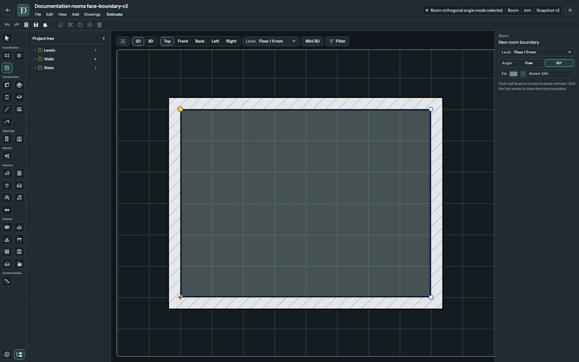
View the full-size boundary drawing screenshot.
The polygon needs at least three distinct vertices and positive area. It cannot cross itself. In 90° mode the closing edge must also be horizontal or vertical; add the necessary corner rather than closing diagonally. Backspace removes the latest unfinished point. Esc cancels the unfinished boundary without deleting an existing Room.
An open-plan zone can use freely placed points for edges that have no Wall. That divides the logical space without creating a partition. Avoid overlapping Room polygons when you need reliable room quantities.
Every Room control
Select the Room in Top or under Rooms in the Project tree. Its right panel contains these controls:
| Control | What it changes |
|---|---|
| Name | The selected Room's tree and inspection name, up to 120 characters. Press Enter or leave the field to apply it. |
| Level | The building Level for a new boundary or the selected Room. Changing it moves the logical assignment and elevation. Interior objects keep their own Levels and lose this Room assignment; the physical enclosure stays in place. |
| Angle → Free / 90° | How subsequent boundary points are drawn. Changing this does not reshape a completed Room. |
| Fill | The identifying source color. The plan uses a muted version at 24% opacity so Walls and other objects remain visible. It is not a floor material. |
| Area | The selected polygon's calculated area in m², displayed to two decimal places. It is read-only. |
| Floor finish, Wall finish, Ceiling finish | Independent surface choices. See Room finishes for every available option and how quantities are measured. |
| Underfloor heating | A separate preliminary hydronic allowance using the full Room floor area. It does not draw heating pipes. |
| Attic under Roof | Roof envelope analysis for a Room under a Roof. See Attic rooms for Roof selection, headroom settings and knee walls. |
The inspection details also report Perimeter, Level and the source fill color. Perimeter and area are derived measurements; they are not dimension inputs.
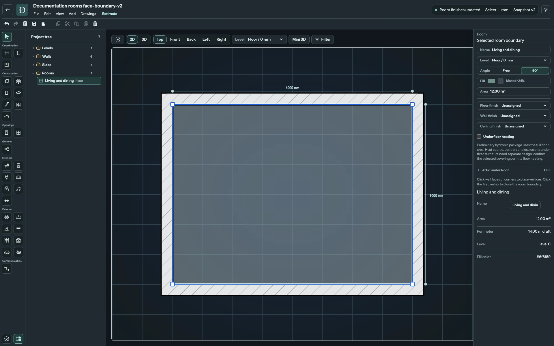
View the full-size selected Room screenshot.
What follows a Wall edit
Snapping uses same-Level physical Wall-face intersections, Wall-face endpoints and points along a Wall face. Slab corners and edges are also available; an eligible Wall target takes priority. Axes and Wall centerlines do not serve as finished Room boundaries.
A snapped vertex records its host reference. Supported edits to that Wall or Slab can recalculate the attached boundary; a free point retains its own location. Deleting a host or producing invalid geometry can leave a reference unresolved. Check the Room and its area after changing the enclosure, particularly when the boundary mixes snapped and free points. Moving an Axis is a separate operation and does not guarantee that the logical Room moves with it.
The current interface has no general Room move grip or completed-boundary vertex editing controls. For a different free boundary, record its name, finish choices and heating setting, delete the Room and draw the replacement. Reapply those settings and check its contents' Room assignment. Use Undo if the result is wrong. Do not use the Floor's vertex controls as instructions for editing a Room.
Visibility, contents and saving
The boundary appears in Top on its active Level. It has no physical boundary in Front, Back, Left, Right or 3D. The tree entry and settings remain available. Changing its fill or finish choices does not create a textured 3D enclosure.
An interior object can be assigned to a Room, but the logical boundary does not act as a group move command. Deleting a Room removes its zoning and finish record; its contained objects are detached from that Room and remain in the project. Physical Walls and Floors are separate objects.
Select Save, reopen the project and check the name, Level, boundary, area, finish choices and heating state. The illustrated Room's name and finish changes were saved and reopened in the example project; your dimensions and choices should match your own intended space.