
A Roof has a covering shell and a framing display. Select it and open Materials and framing to set their materials, thickness, spacing and visibility.
Configure the construction
| Setting | Effect |
|---|---|
| Cover thickness | Thickness above the Roof's underside reference, at least 20 mm. Check the resulting top surface in a side view. |
| Cover | Material assigned to the roof covering. Choose the material that matches your intended surface. |
| Framing system | None, Flat joists · schematic, Timber rafters · schematic or Truss array · schematic. Availability depends on the Roof geometry. |
| Frame mat. | Timber or steel material used for framing. It does not supply a structural member design. |
| Spacing | Target spacing of the modeled members, at least 50 mm. Inspect the resolved layout around edges and openings. |
| Show shell / Show framing | Independent display controls. Hiding either helps inspect the other. |
In main 3D, Show shell hides the covering, dormer bodies and the attic interior lining. Inclined Roof windows remain visible when their own Visible setting is on. Generated gable and perimeter walls remain controlled by their wall settings. Show framing hides only the framing display; it does not remove a resolved layout's depth from attic headroom analysis.
The Roof's eye in the project tree hides the whole Roof. If the Roof is unexpectedly absent in a view, also check Filter → Levels through: display follows its bound Level, including a raised Roof's Level rather than only its visible height.
See materials and types to distinguish material definitions, assemblies and assigned element types. A material's appearance, a covering's thickness and a finished-element price describe different properties.
Choose a framing system
| Roof type | Available schematic systems |
|---|---|
| Flat | None or Flat joists · schematic. |
| Gable | None, Timber rafters · schematic or Truss array · schematic. |
| Shed, Hip, Pavilion, Custom planes | None or Timber rafters · schematic. |
The menu follows the Roof type; the resolved shape still determines whether the system can be built. Joists require one horizontal plane. A truss array requires one rectangular ridge part with two gable ends. Rafters require all exposed faces to be inclined: a mixed flat-and-pitched roof does not receive partial framing. A selected system must also fit the openings. In Frame mat., choose a timber or steel material. This changes the assigned material without changing the selected system's name into a new structural system.
Compare spacing and materials
In this Gable example, hiding Show shell exposes the same framing at 600 mm and 1,200 mm spacing. The modeled member count changes from 45 to 29, including edge and connection members; it is not simply the roof length divided by spacing. These values illustrate the control rather than a structural recommendation.
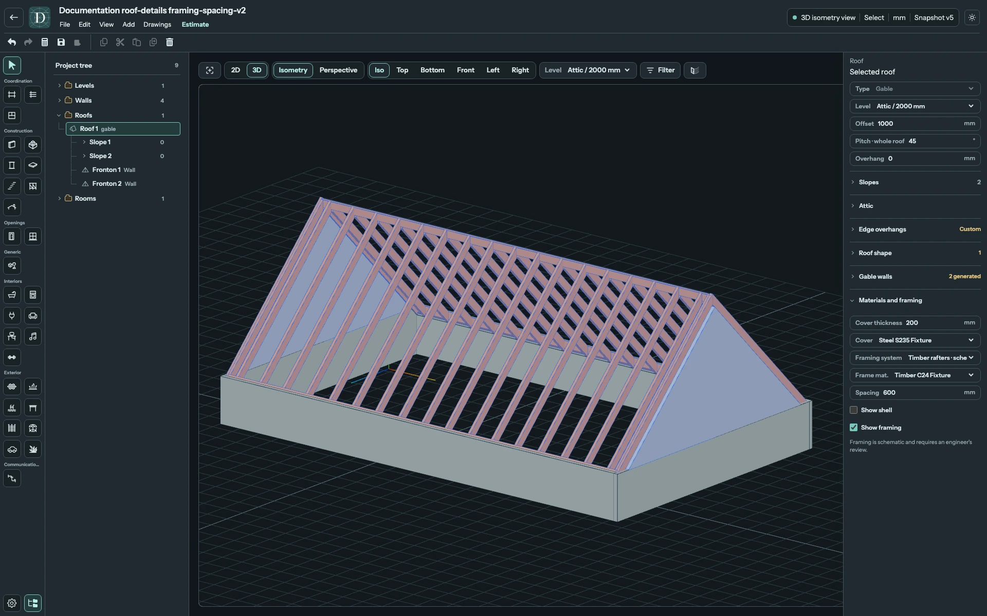
View the 600 mm spacing example at full size.
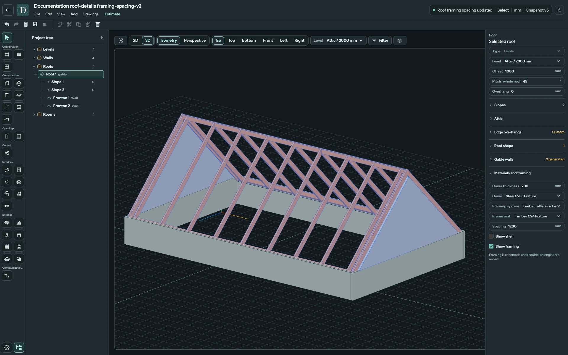
View the 1,200 mm spacing example at full size.
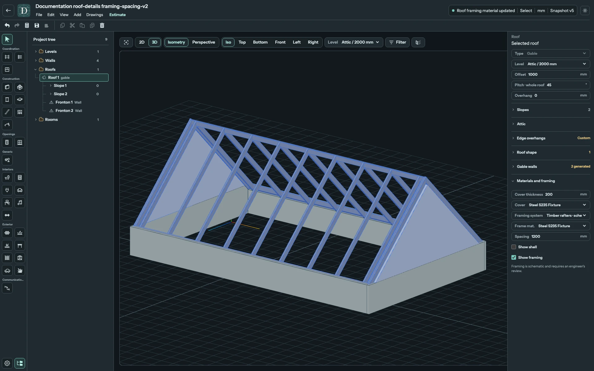
View the steel material example at full size.
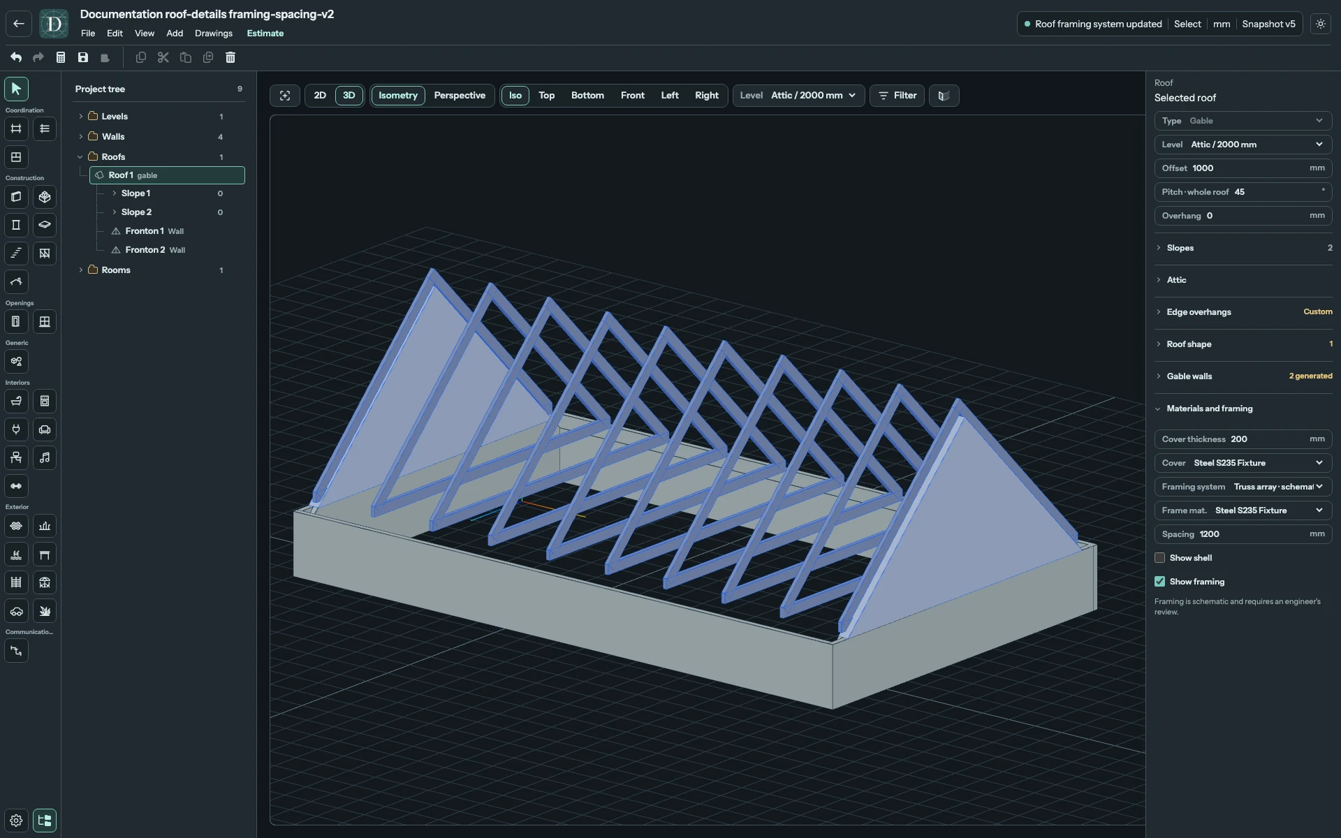
View the truss example at full size.
Inspect the result
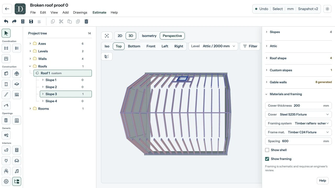
View the shell-hidden framing at full size.
Use Show shell to expose the framing, then inspect it in 3D and side views. Check that members follow the intended slope and that the layout responds to Roof windows, dormers, valleys and part connections. A supported Roof window keeps the original rafter or joist lines and spacing, cutting affected members at local headers and adding short doubled side members between them. Unsupported local framing and truss cuts are blocked.
Read any geometry or framing message beneath the controls after changing the shape or adding an opening. The selector offers the systems compatible with the Roof type; a valid surface alone does not guarantee that every requested framing arrangement is supported.
What the display establishes
The framing is schematic and requires an engineer's review. A visible rafter or truss does not establish its section, load capacity, connections, bracing or code compliance.
Check the drawing view settings when a sheet omits a visible model layer. In the estimate, review quantities, selected definitions and missing prices. A drawing or priced row does not replace structural verification.