Select a Roof, then open Slopes to work on a physical surface or Roof shape to work on the parts that generate those surfaces. A part can generate several slopes; a displayed slope can also include several connected patches. The two lists therefore need not have the same count.
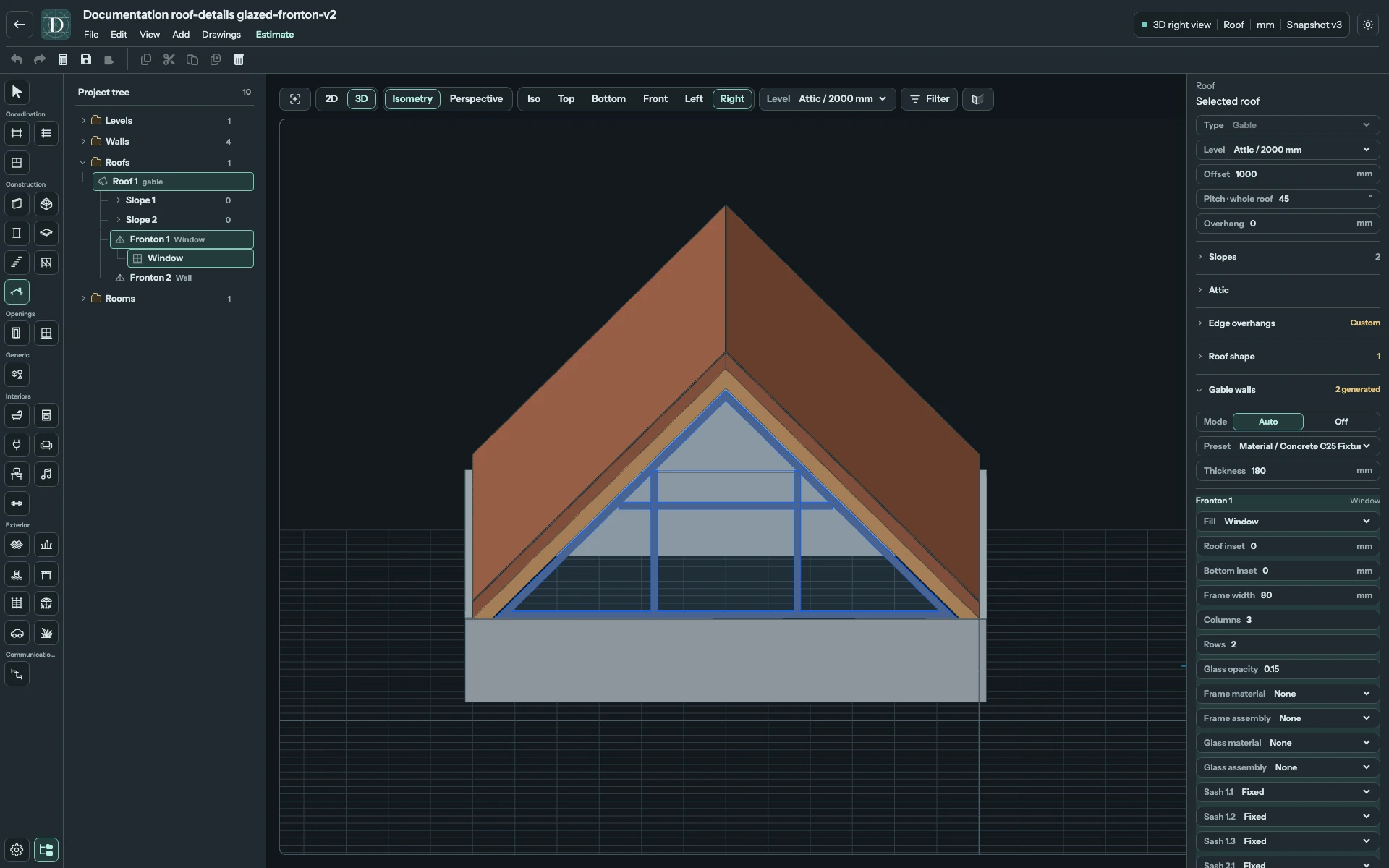
For a fronton window, open Gable walls, select Fronton N, and choose Fill → Window. Window type → Full contour exposes Roof inset and Bottom inset; Rectangular window exposes Width, Height, Sill above base and Horizontal offset. See roof-end walls and glazing for their conditions and assembly fields.
Select a slope and understand its controls
Hover a Slopes row to find its surface, then click the row. The face is highlighted in the model and its pitch and edge settings appear in the panel. You can also click an available face in Top or expand the Roof in the project tree and choose Slope N. These controls share one selected slope. Esc first clears the face selection while keeping the Roof selected.
Inclined and dormer windows appear beneath their supporting slope in both Slopes and the project tree. Use Add window inside the slope, choose Roof window or Dormer window, and select the dormer shape when applicable. Confirm Add window to create a complete window automatically. Open a child row to edit all its settings or delete it in the same place. Selecting a child keeps its Roof as the owner; it does not turn the window into an independent Roof.
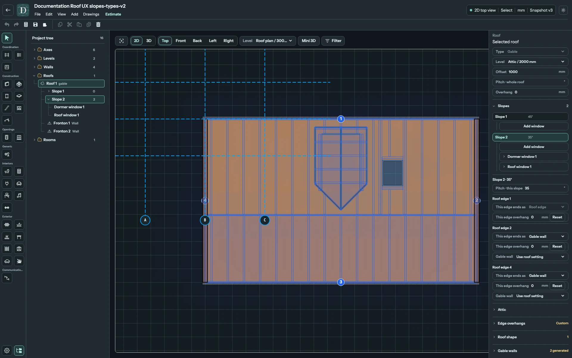
View the selected-slope controls at full size.
Change one slope's pitch
Select a slope, enter an angle in Pitch · this slope, then press Enter or leave the field. Inspect the surface in a side view and 3D. A successful edit changes the surface geometry; the angle is not just a label. Invalid geometry or a conflict with a hosted opening or Roof-trimmed Wall can reject the edit and retain the prior value.
Angles use 0.1° precision. A plane accepts 0° through 89.9°; a pitched generating slope or reference pitch accepts 0.1° through 89.9°. Zero therefore works for a plane, but cannot flatten an individual Gable, Hip or Pavilion generating slope.
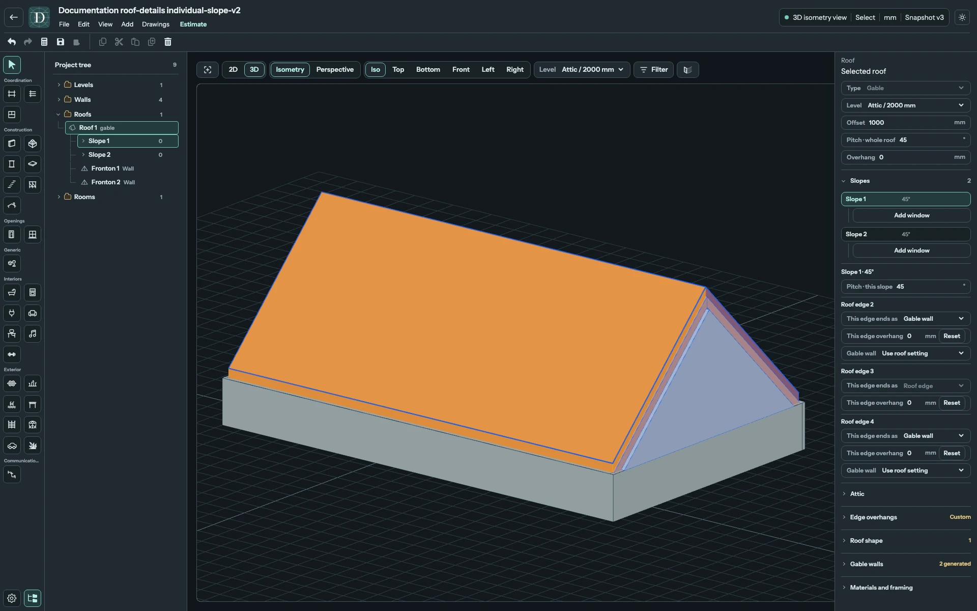
View the original slope geometry at full size.
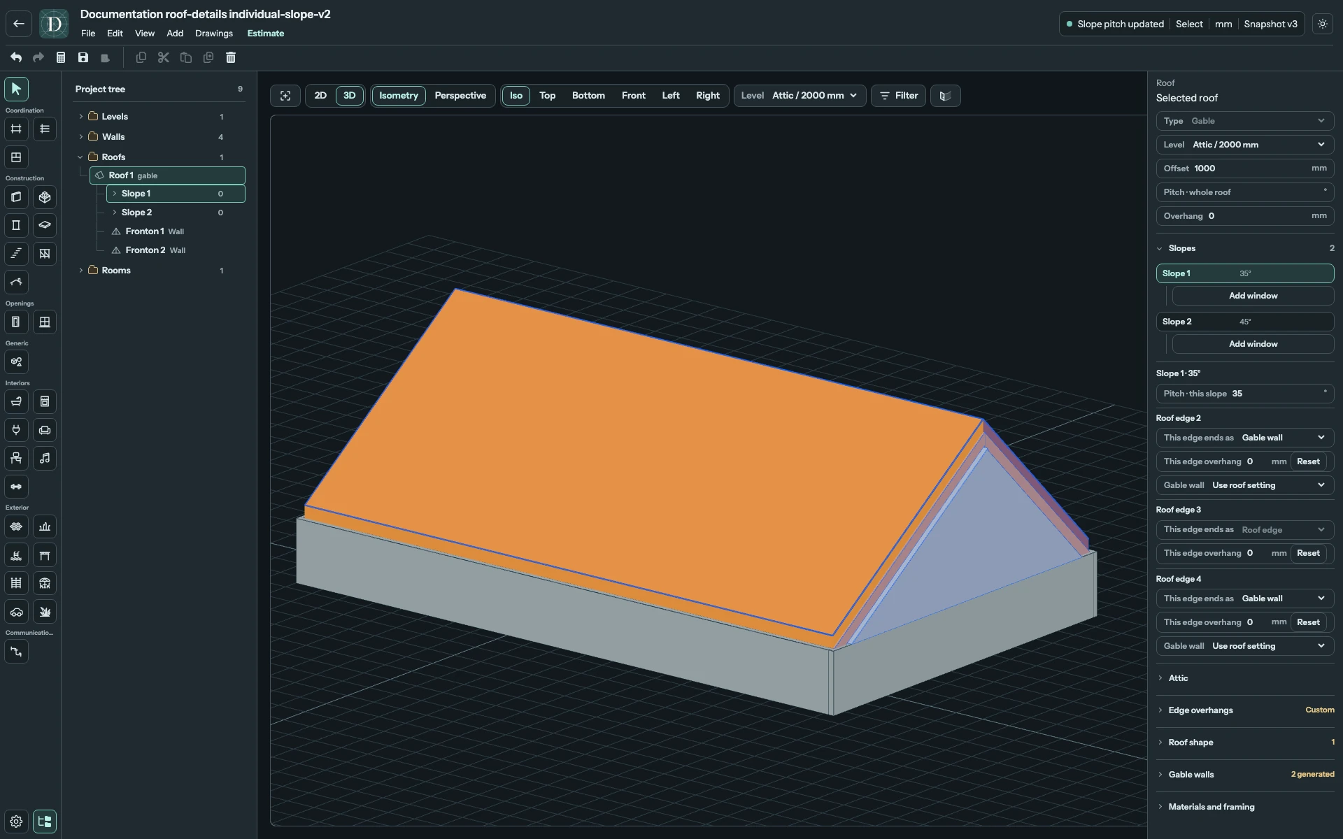
View the changed slope geometry at full size.
| Shape | Effect of the selected-slope pitch |
|---|---|
| Flat, Shed, or a Custom plane | Changes the selected plane about its reference edge. A plane can have a zero pitch. |
| Gable, including a sloping ridge end | Changes that generating slope or hip end; the other authored pitches stay as set. The ridge and junction geometry is recalculated. |
| Hip | Changes the selected eave-generated slope. Different angles produce a correspondingly different resolved roof, including on a supported irregular contour. |
| Pavilion | Uses the selected slope as a reference to set the common apex height. The other slopes still meet that apex and can change angle. |
Pavilion angles are therefore coupled: they cannot all be chosen independently while retaining one shared apex. Use the apex policies below when you need to control the common point or its height.
Pitch · whole roof remains a separate Roof-wide command. A mixed-pitch roof can show an empty whole-roof field; entering a value there makes its applicable pitches uniform. Selecting a slope does not narrow that command to one face.
Change a slope's edges
| Control | What it changes |
|---|---|
| This edge ends as / End shape | The supported end condition: Roof edge, Gable wall or connection to another roof part. Available choices depend on the edge and part. |
| This edge overhang | Non-negative horizontal distance beyond that particular boundary, measured in plan. Reset removes the override and uses the Roof value. |
| Gable wall | Whether the selected end follows the Roof setting, creates a wall automatically, or has no wall. |
| Make this edge a gable | Converts a supported sloping end to a gable. It is shown only when that conversion is available. |
A Connected roof edge represents a connection. Its effective overhang is zero and the distance input is disabled. Check both parts' elevations and the resolved geometry after changing a role.
Add and change roof parts
- Select the Roof in Top and open Roof shape.
- Choose New roof part, or First roof part when the panel asks you to define the roof shape.
- Use Add roof part or Define roof shape. Trace the new closed contour. For a ridge, start with a rectangle. Cancel exits the unfinished placement.
- Select the resulting part in the list. Inspect its boundaries, the combined surface and the connection to the existing roof in Top and 3D.
| Part shape | Use |
|---|---|
| Slopes on every side | Perimeter slopes resolving into hips and valleys. |
| Ridge with end walls | Two main slopes with editable ridge-end conditions. |
| Slopes to one apex | Pavilion geometry with explicit apex controls. |
| Single slope | One plane with a pivot edge and rising side. |
For an existing part, select Change shape, choose New shape and its draft Pitch · this part, then Apply when the replacement is valid. Cancel keeps the original. Apply is unavailable for an incomplete replacement or the unchanged shape. A rejected replacement leaves the original intact; read the message, including any conflict with Walls that follow the Roof. This draft pitch belongs to the replacement shape. Use Slopes → Pitch · this slope to edit an existing surface.
To edit a part's boundary roles directly, select the part and clear the selected slope. Its Edge N role controls then appear in Roof shape; the choices depend on that part's shape. Selecting a slope exposes the related Slopes controls instead.
Select a ridge part to use Rotate ridge 90° or set Ridge end 1 and Ridge end 2 to Gable wall, Roof slope or Connected roof. Remove a part with its Remove roof part action only when the resulting roof is still valid; the last remaining part cannot be removed; review attached windows and dormers before removing their supporting geometry.
Compare a connected roof in Top and 3D
This example adds a narrow Gable branch to the same Roof. The branch overlaps the main footprint so the resolved junction can connect the two parts. A connection must meet at the same XYZ elevation or stay hidden beneath the other part; placing two unrelated contours next to each other does not make a valid junction.
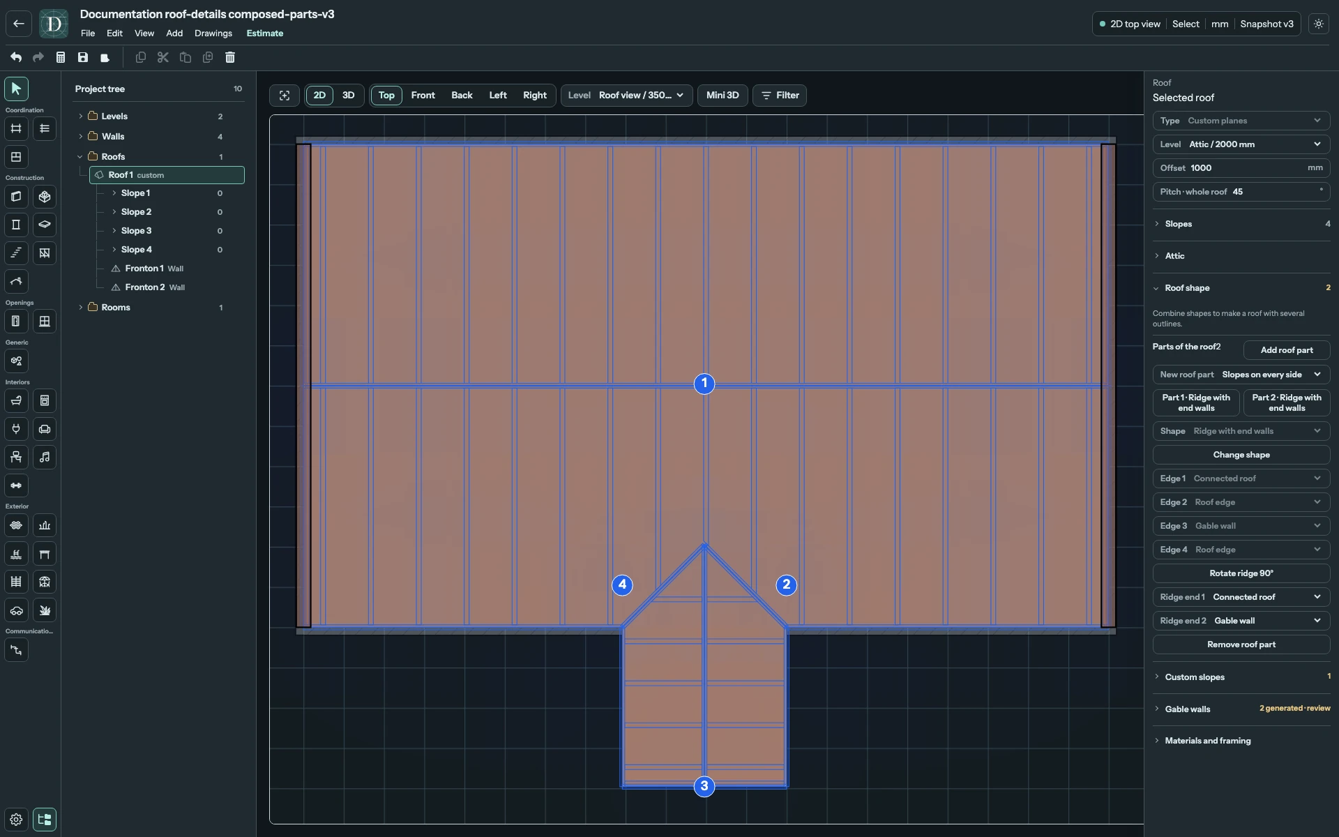
View the composed roof in Top at full size.
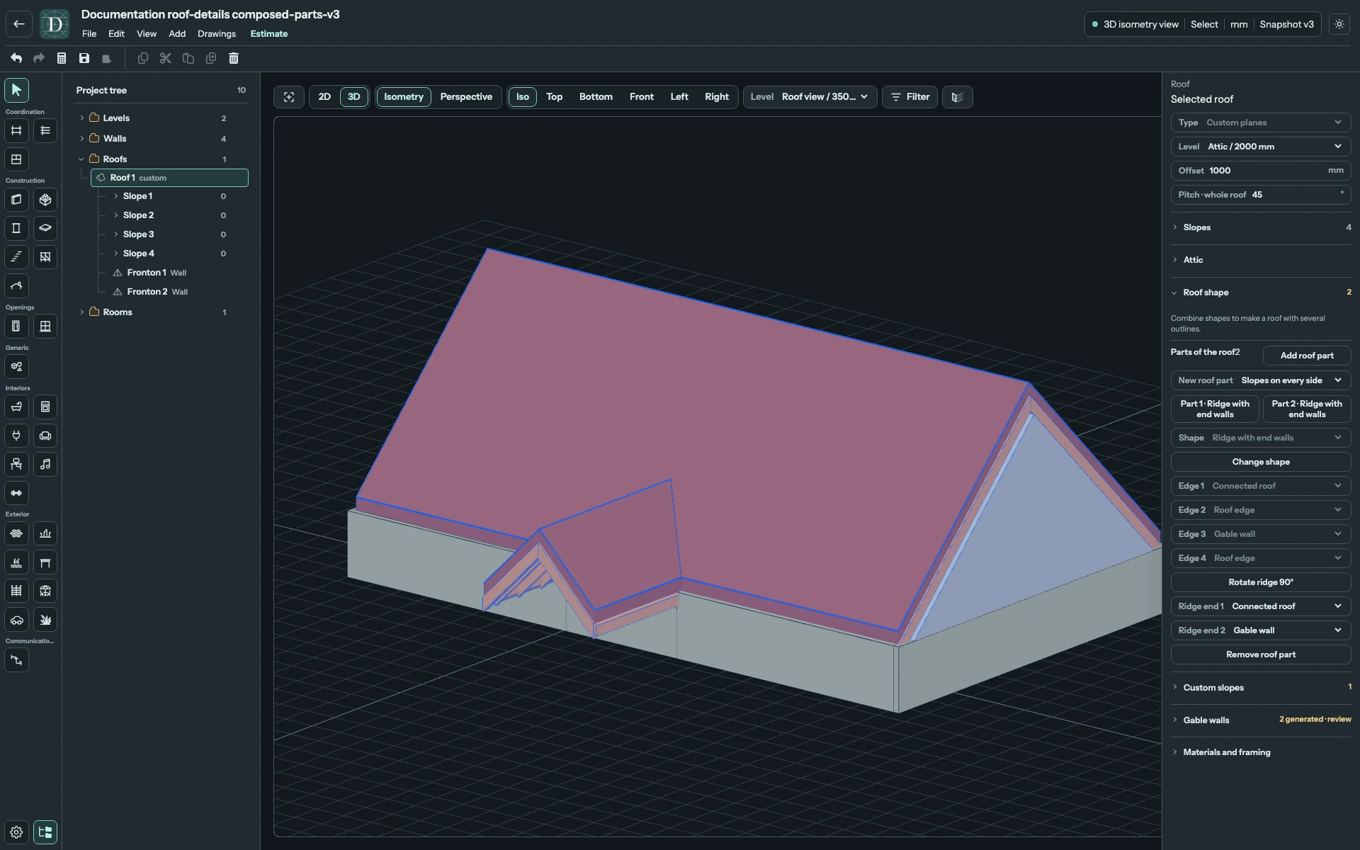
View the composed roof in 3D at full size.
Set a Pavilion apex
Select the single-apex part. Automatic kernel chooses a suitable point inside the supported footprint. To use Explicit XY, enter Explicit apex X and Explicit apex Y, then select Apply explicit point. Choosing the policy alone asks for coordinates; it does not commit a point. The coordinates are model coordinates in the project's length unit. The point must lie strictly inside the supported interior region; a point on its boundary is rejected.
Apex height offers three policies:
The outer datum used below is the Roof's reference covering elevation: its Level elevation plus Offset and Cover thickness. Explicit apex height and a Custom plane's Pivot offset are vertical distances from that reference. For example, Level 3000 mm, Offset 200 mm and Cover thickness 100 mm give an outer datum of 3300 mm; an explicit apex height of 1500 mm places the apex at 4800 mm.
- Uniform pitch asks all eligible eaves to produce the same requested pitch. A non-square or irregular footprint may not admit that solution.
- Reference eave uses one selected eave and its reference pitch to determine the height. Selecting a boundary under Reference eave applies that policy using the current pitch; other slopes can have different resolved angles.
- Explicit height uses Explicit apex height, measured above the roof's outer datum. Enter the height and select Apply explicit height; choosing the policy alone does not commit a height.
Reference pitch is shown while Explicit height is active. To enter a different reference pitch through these advanced controls, first apply an explicit height. Keep that policy active while choosing an edge in the Reference eave field and entering Reference pitch, then select Apply reference eave + pitch. That action switches the part to the Reference eave policy. Alternatively, select the desired surface under Slopes and use Pitch · this slope to make that surface the height reference.
Use the policy that describes your roof. If the panel reports an incompatible apex or height, change the policy or point instead of accepting a plausible-looking unresolved shape.
Work with Custom planes
In Custom planes, open Custom slopes and use Add slope. Draw a closed contour for each plane. The first edge is its pivot/eave reference; the drawing order determines which side rises. Pivot offset moves that reference vertically relative to the roof datum. The plane's drawn perimeter defines its extent.
Matching outlines are not enough for a connected roof: shared boundaries must also meet at the same height. Check side views and 3D for steps, gaps, overlaps and the direction of rise. Remove an unwanted plane using its row's remove action. The last remaining Custom slope cannot be removed.
To give lower and upper planes different pitches, select each surface under Slopes and edit Pitch · this slope. Use its Pivot offset under Custom slopes to place the reference edge at the intended height. For a broken roof, check that the lower and upper surfaces meet at the pitch break. Entering Pitch · whole roof changes the applicable angles together, so use the individual control when adjusting just one surface. See the broken-roof window example.
Fill roof ends with Walls or glazing
Open Gable walls. Mode → Auto generates eligible roof-end fills; Off disables the upper fills. Preset selects their material or wall assembly. Thickness, at least 40 mm, describes the generated walls. Preset and Thickness are disabled only when Mode is Off and Build knee walls is also off. When that checkbox is on, the lower perimeter band remains and uses these same settings. See walls below a raised Roof. A sufficiently high adjoining Wall can replace a derived fill. Generated fills belong to the Roof rather than acting as independent Walls in the tree.
For an available Fronton N, choose Fill → Wall or Window, then select its row to reveal the window fields. Window type offers two different openings:
| Window type | Shape and position controls |
|---|---|
| Full contour | Glazing follows the roof end's resolved profile. Non-negative Roof inset and Bottom inset reduce that profile. |
| Rectangular window | One rectangular opening leaves wall around it. Set positive Width and Height, non-negative Sill above base, and signed Horizontal offset from the fronton's center. |
Sill above base is measured from this fronton's base, which can differ from the attic floor. Positive and negative Horizontal offset move the opening to opposite sides of its center. The complete opening and frame must fit the resolved end wall. A rejected type, size or position keeps the previous valid setting; inspect the geometry message instead of expecting the editor to shrink an authored window.
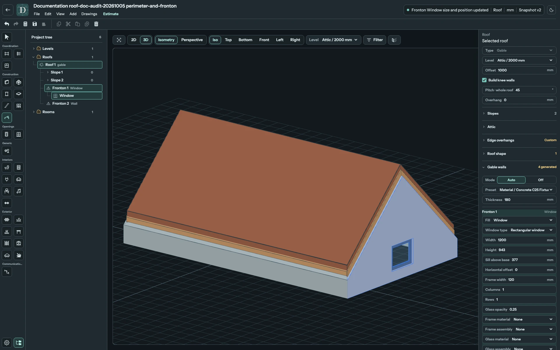
View the rectangular fronton window at full size.
Both window types share the remaining assembly fields. Frame width is at least 10 mm and must leave a valid glazed profile. Columns and Rows each accept an integer from 1 to 12 and divide the profile into panes; each Sash offers Fixed, Left hung, Right hung or Tilt & turn. Glass opacity accepts a fraction from 0.05 to 0.95, so 0.25 means 25% opacity. The Dormer panel displays its separate opacity field as a percentage.
Choose Frame material or Frame assembly for the frame, and Glass material or Glass assembly for the glazing. Material and assembly are alternative assignments for each part. To switch from a material to an assembly, first set that part's material to None; to switch back, clear its assembly first. Selecting both at once is rejected, and the previous assignment stays in place.
A glazed fronton is a roof-end fill. An ordinary Window is placed in a Wall, an inclined window lies in a slope, and a dormer projects out of the roof. Choose the appropriate host before trying to move or resize it.