
Use Generic → Shapes for a neutral volume when no named model element fits your sketch. A Shape can represent an occupied envelope, a simple object or a placeholder. Its dimensions and color do not give it the construction, material or estimate meaning of a Wall, Slab or catalog object.
Choose and place a Shape
- Choose 2D → Top and the working Level.
- Open Shapes and choose Box, Cylinder, Sphere or Wedge.
- Set the dimensions, Level, Base offset and appearance in the right panel.
- Position the complete preview and click. Choose Select or press Escape when finished placing objects.
- Select an existing Shape in the viewport or Generic Objects in the Project tree to edit it.
A loose Shape belongs to the Site. Its base elevation is Level + Base offset, independent of nearby Rooms and surfaces. Raising a Terrain or moving furniture beside it does not move the Shape.
| Shape | How the dimensions affect it |
|---|---|
| Box | Width and Depth form the horizontal rectangle; Height sets the vertical dimension. |
| Wedge | Width and Depth form the footprint; Height sets the high end of the sloping volume. Rotate it to change the direction of the slope. |
| Sphere | Width, Depth and Height are independent diameters. Equal values produce a sphere; unequal values produce an ellipsoid. |
| Cylinder | Upright, Height sets the axis length and Width/Depth are the horizontal section diameters. Lay on side turns the cylinder axis horizontally; see the example below. |
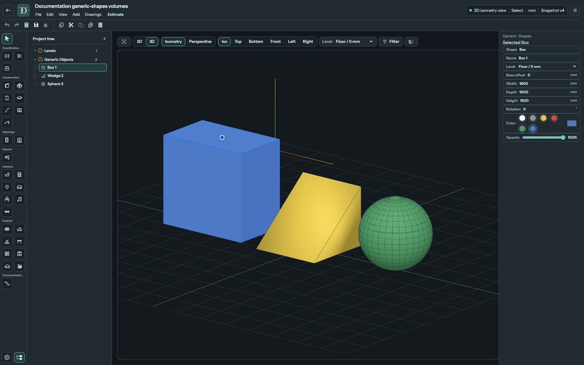
View the three volumes at full size.
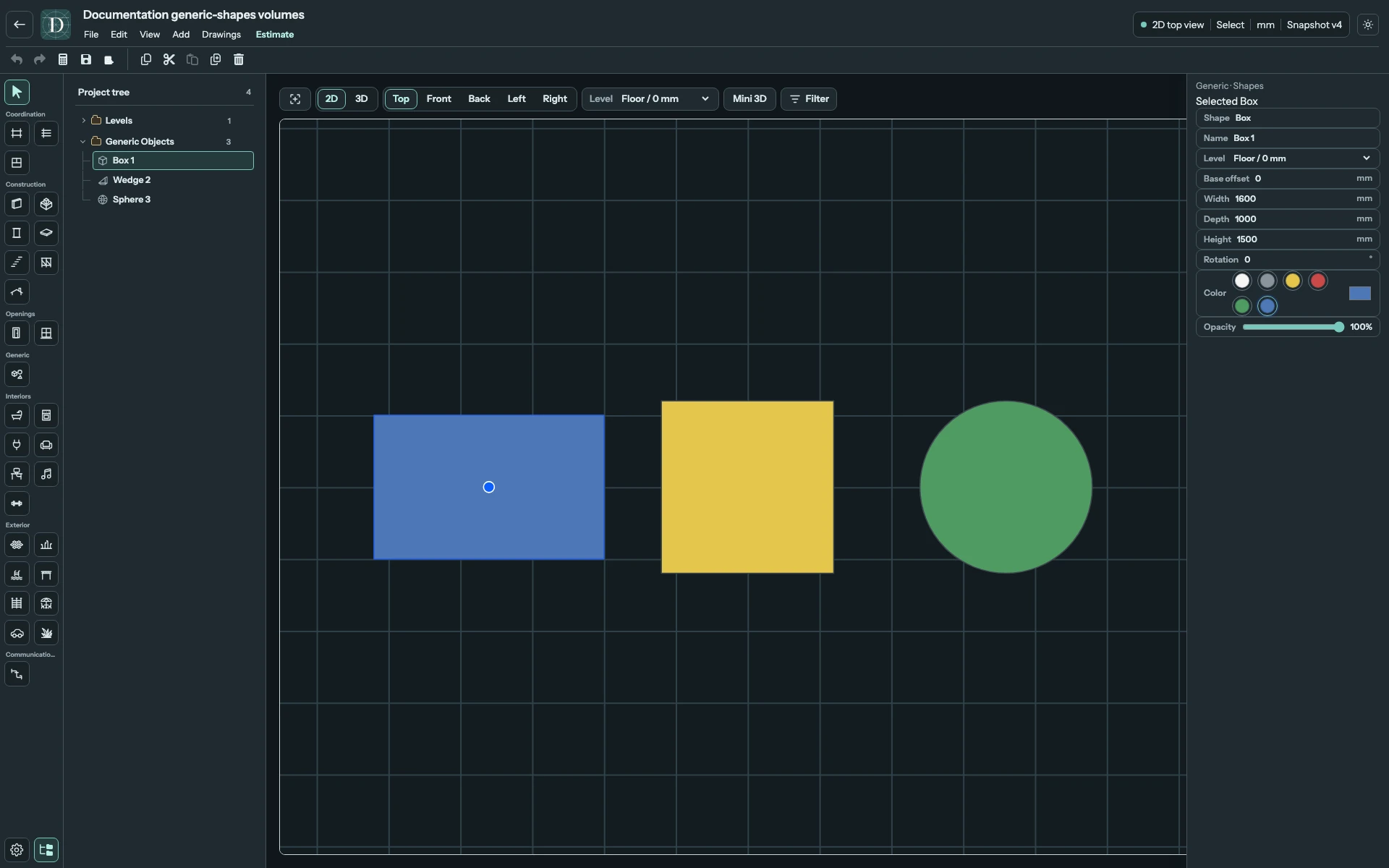
View the footprints at full size.
Configure geometry and appearance
| Setting | What it does |
|---|---|
| Shape | Displays the chosen form. To use another form, place it from the catalog; this output is not a form selector. |
| Name | Identifies an existing instance. Enter up to 120 characters and confirm the field; the Project tree uses the same name. The field appears after placement. |
| Level | Required reference for the bottom elevation. |
| Base offset | Signed vertical distance from that Level, entered in the displayed length unit. |
| Width / Depth / Height | Three independent dimensions. Each accepts 10 mm to 1,000,000 mm; those limits are 0.01–1000 m regardless of the displayed unit. |
| Lay on side | Cylinder only. Turns its axis from vertical to horizontal without changing the three stored dimension values. |
| Rotation | Horizontal orientation in degrees. Use the field or supported rotation handles for a loose Shape. |
| Color | Choose White, Gray, Yellow, Red, Green or Blue, or use the custom color control beside the swatches. This is visual color, not a material assignment. |
| Opacity | Sets transparency from 15% to 100% in one-percent steps. 100% is opaque. |
Invalid dimensions leave the Shape at its previous valid size. Resize through the dimension fields. Use the center movement handle to move the complete object; changing Width does not move a separate face.
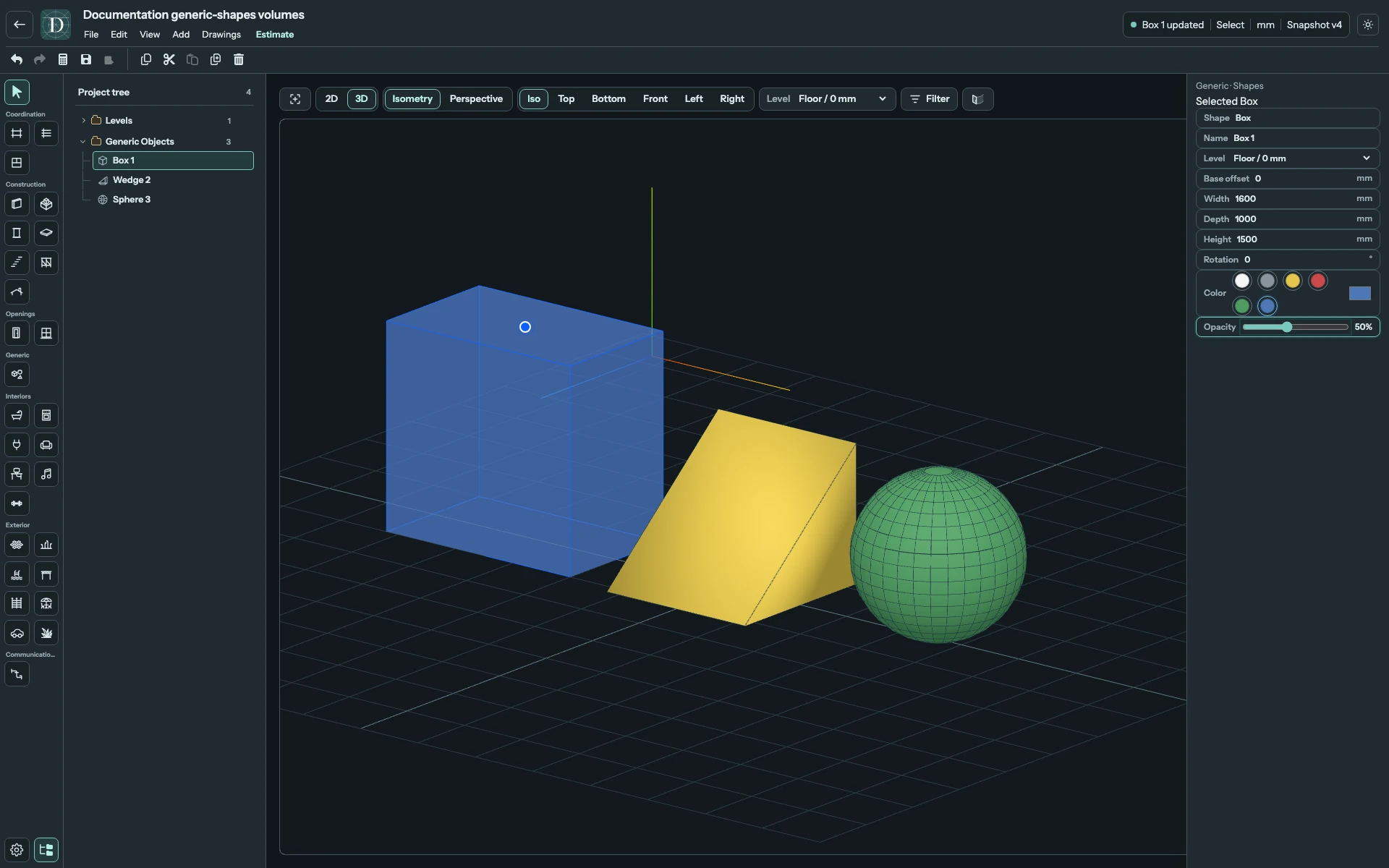
View the transparency example at full size.
Lay a Cylinder on its side
Start with Width 1000 mm, Depth 1000 mm and Height 2000 mm. Upright, this is a cylinder with a 1000 mm circular section and a 2000 mm vertical axis.
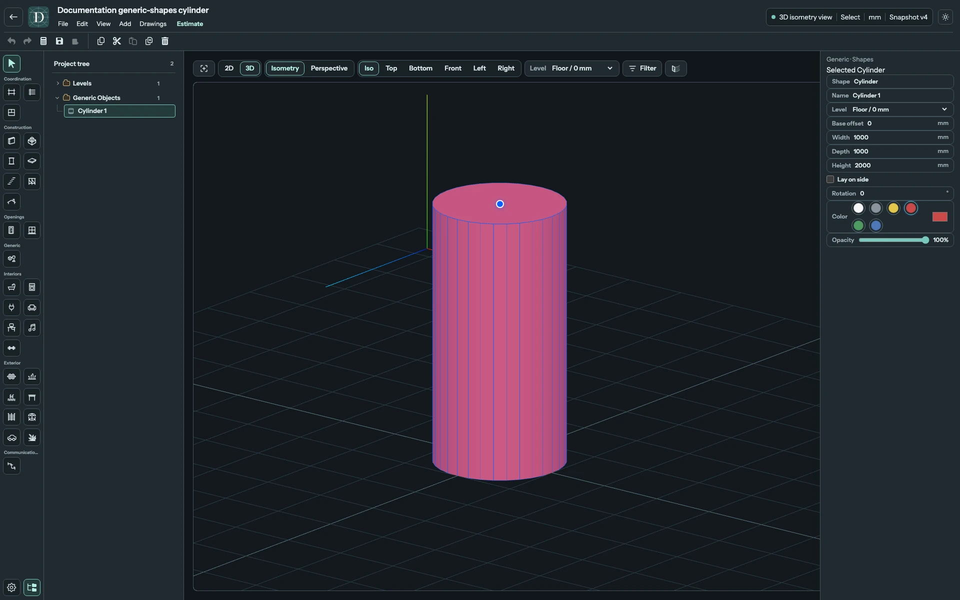
View the upright Cylinder at full size.
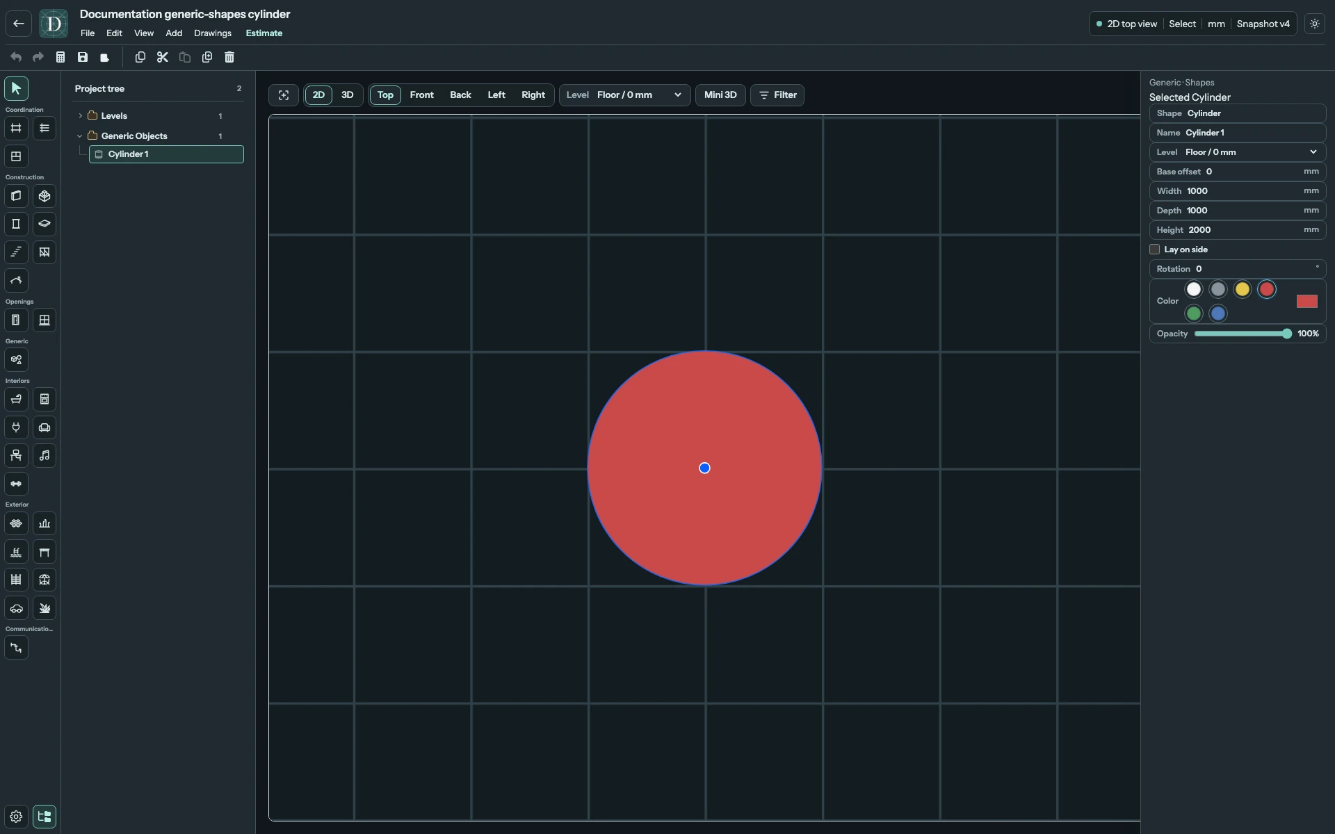
View the upright footprint at full size.
Check Lay on side. The original Height now becomes the horizontal cylinder length; Width becomes its vertical section diameter and Depth remains the other section diameter. The field names and stored values stay the same. Rotate the loose Shape to turn the horizontal axis across the plan.
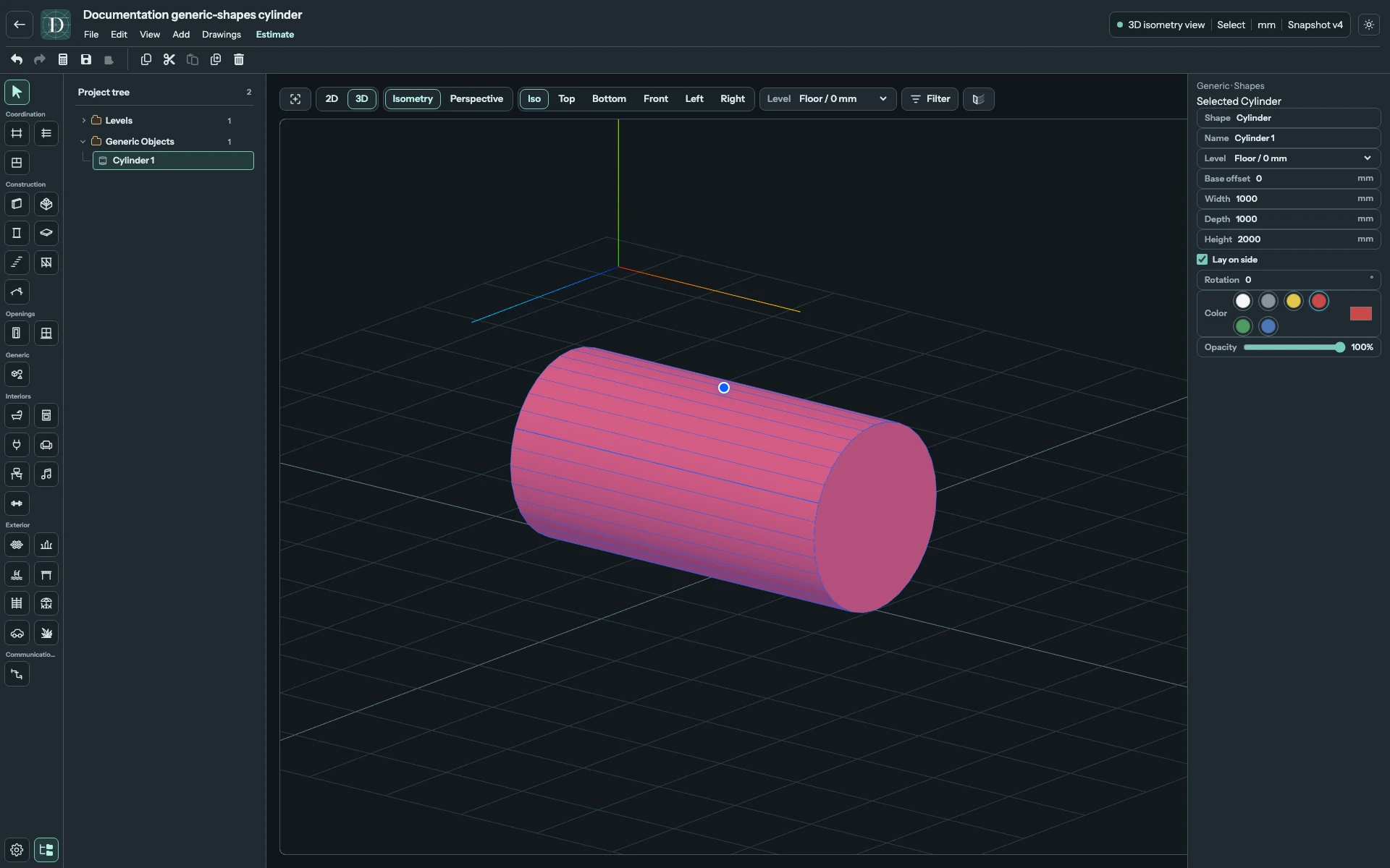
View the horizontal Cylinder at full size.
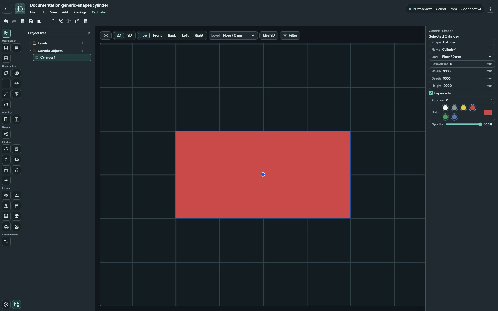
View the horizontal footprint at full size.
Equal Width and Depth keep the cylinder section circular in either orientation. Unequal values make that section elliptical. The dimension values in these examples demonstrate the controls; set the envelope needed by your own design.
Group, undo and save
To transform several Shapes together, use Generic Groups. A grouped child retains its dimensions and appearance controls, but individual movement, rotation, Cylinder orientation and deletion are restricted. Ungroup first when you need those operations.
Undo reverses an accepted edit; Redo reapplies it. Select a loose Shape and use Delete to remove it; Undo restores it. Save and reopen to retain its Name, dimensions, Level, offset, orientation, color and opacity. Use Top for placement and 3D for volume; Generic Shapes are excluded from architectural 2D side views.