
Terrain adds a grass-like horizontal surface for the site layout. Draw its boundary in 2D → Top, then place the whole surface vertically with Level and Offset. The current tool creates one flat surface; it does not sculpt a surveyed landscape or assign a different elevation to each corner.
Draw the site surface
- Choose 2D → Top, then Exterior → Terrain in the tool rail.
- Choose Level and enter Offset in the right panel.
- Set Angles → Free for arbitrary directions or 90° for orthogonal boundary segments.
- Click the boundary points in order. Use at least three corners, then click the first point to close the polygon. Avoid crossing edges.
- Choose Select and select the finished surface in the viewport or Exterior → Terrain in the Project tree.
During drawing, Backspace removes the latest draft point and Escape cancels the unfinished chain. Opt-in temporary alignment guides help place points; they do not attach the Terrain to those references. See alignment guides.
Understand the surface in Top and 3D
The example has five boundary corners and a separate strip of Pavement beside it. The grass surface itself has no modeled soil thickness. The pavement is a different object with its own thickness, materials and elevation.
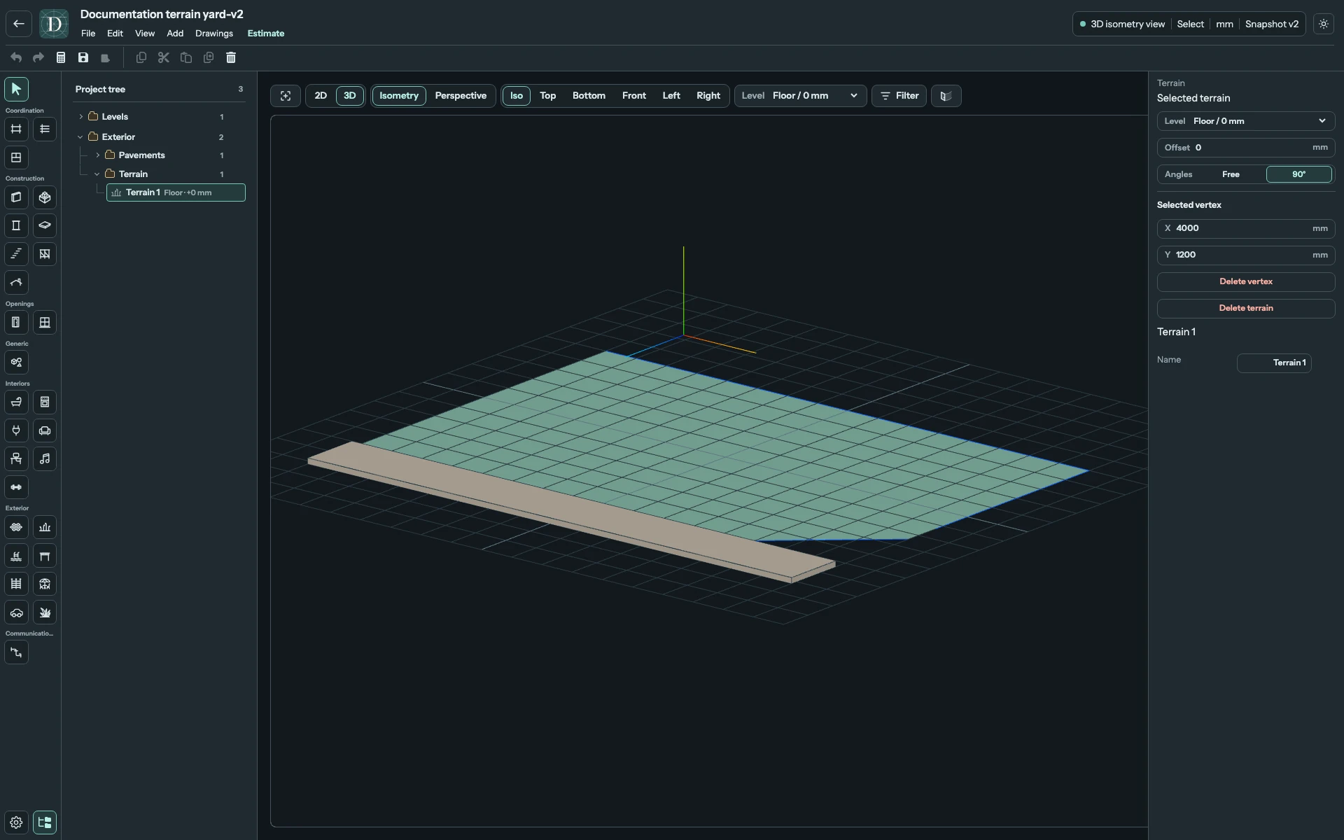
View the site surfaces at full size.
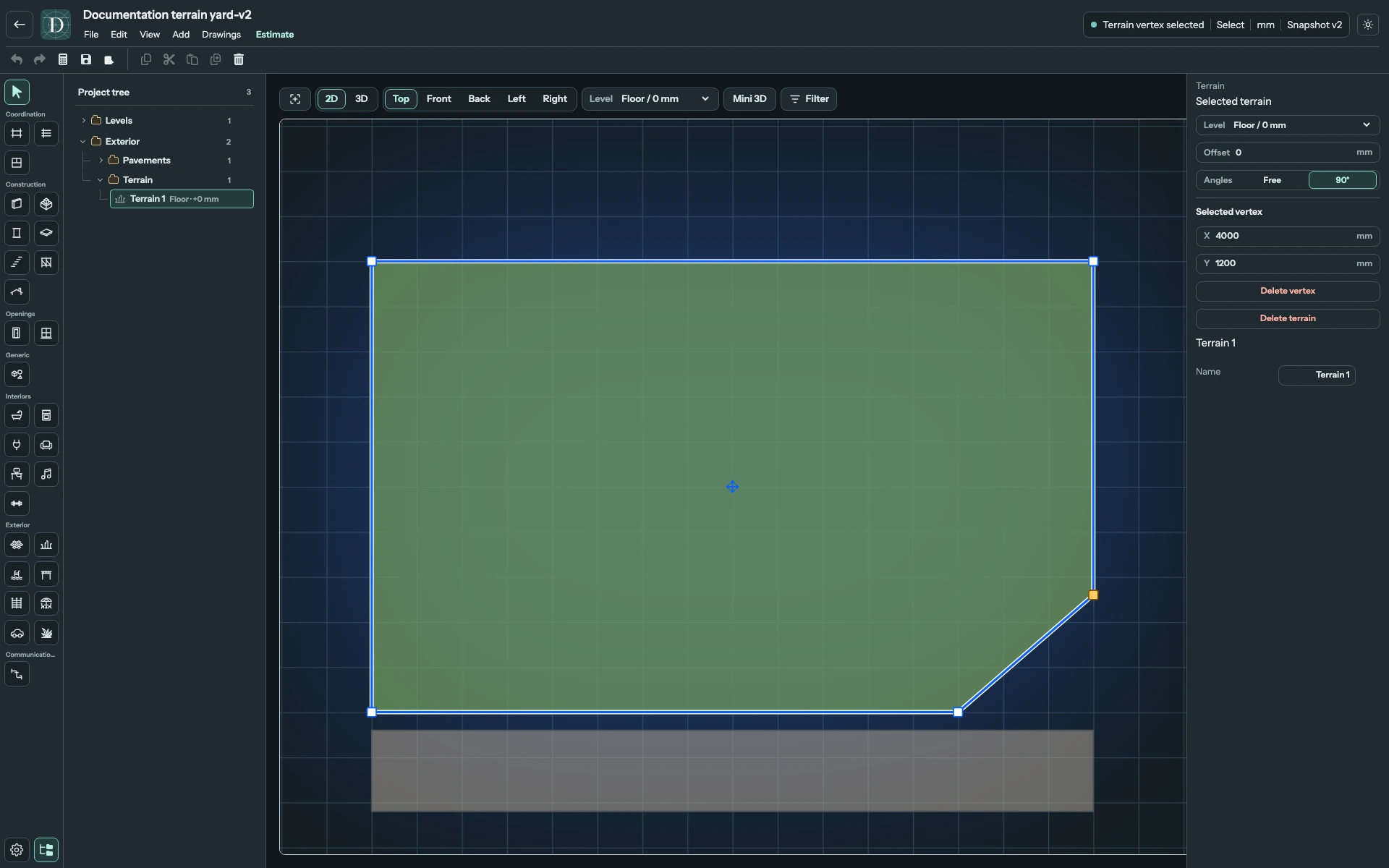
View the boundary and selected vertex at full size.
Every Terrain control
| Control | What it changes |
|---|---|
| Name | Renames the selected surface in the object inspector below the Terrain settings. The Project tree uses the same name. |
| Level | Existing reference Level for the whole surface. Its elevation plus Offset sets the Terrain elevation. |
| Offset | Signed vertical distance from the selected Level, entered in the displayed length unit. Changing it lifts or lowers the entire flat surface. |
| Angles → Free / 90° | Direction constraint for drawing a new boundary. Switching it does not straighten or reshape a finished surface. |
| Selected vertex → X / Y | Exact plan coordinates of one selected boundary vertex. Other vertices retain their coordinates. |
| Delete vertex | Removes the selected boundary point. If fewer than three corners remain, it removes the entire Terrain; Undo restores it. |
| Delete terrain | Removes the complete selected surface. Use Undo to restore it. |
Terrain belongs to the Site even when it references a building Level. It does not belong to a Room. There is no separate material selector, soil thickness, slope control or per-vertex elevation in this panel.
Move and reshape the boundary
In Top, drag the center movement handle to translate the complete surface. Drag one corner handle to reshape the boundary, or click that handle and edit its X/Y fields for a precise location.
To add a corner, hover an edge of the selected surface and click its plus handle. The new vertex splits that edge; select or drag it to shape the boundary. This action is useful when adding a recess or extending an existing yard.
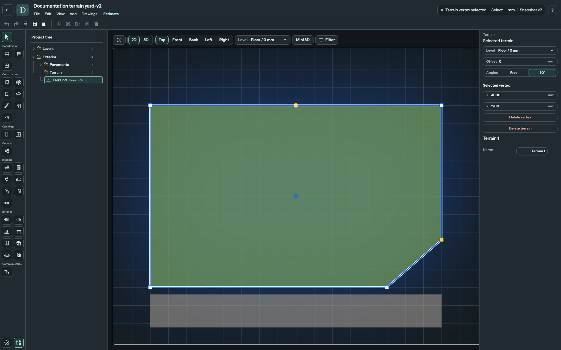
View the insertion control at full size.
Crossing edges or duplicate neighboring points are rejected, preserving the previous valid surface. Removing a corner so that fewer than three remain, or moving the corners into a zero-area straight line, removes the entire Terrain. Undo restores that surface or reverses another accepted edit; Redo reapplies it.
Change elevation without moving neighboring objects
In this example, changing Offset from 0 to 600 mm raises the Terrain surface by 600 mm. The paved strip beside it retains its own elevation. Vegetation, furniture, buildings and other surfaces likewise keep their own Levels and offsets; they are not carried by the Terrain automatically.
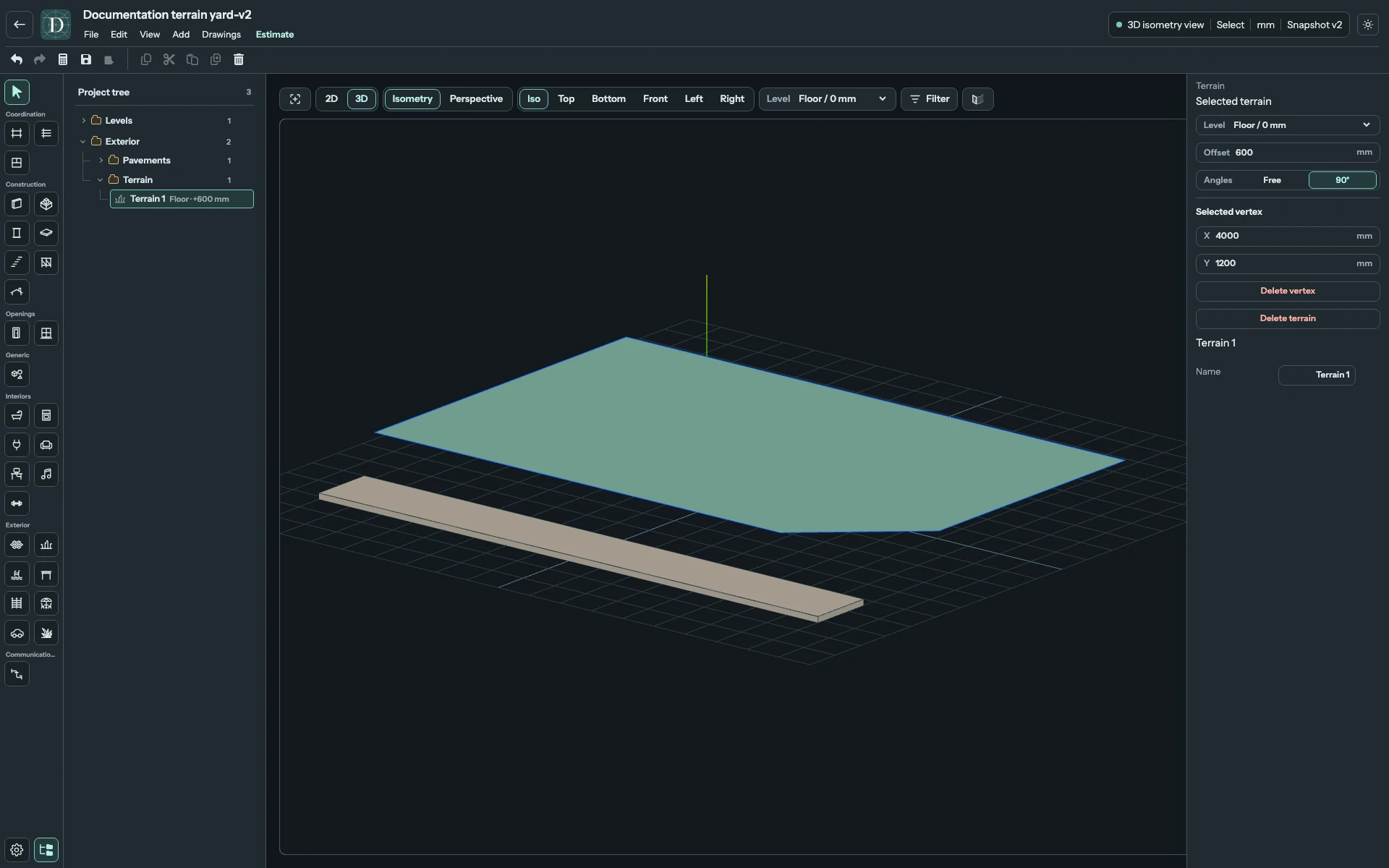
View the elevation change at full size.
Use Top for boundary editing and 3D to inspect elevation and neighboring surfaces. Terrain is omitted from architectural 2D side views. A Pool whose complete outer footprint, including its deck, fits inside Terrain can cut an opening when the Terrain is above the pool's outer bottom. Inspect their overlap in 3D rather than assuming that two overlapping surfaces have been combined.
Save before leaving and reopen to retain the boundary, Level and Offset. Terrain supplies visual site context, not contour elevations, earthwork quantities or a soil design.